EasyManuals Logo

Mercury Optimax 115 User Manual

Mercury Optimax 115
522 pages
To Next Page IconTo Next Page
To Previous Page IconTo Previous Page
Page #350 background imageLoading...
Page #350 background image
POWER TRIM
90-855347R1 JANUARY 1999 Page 5B-45
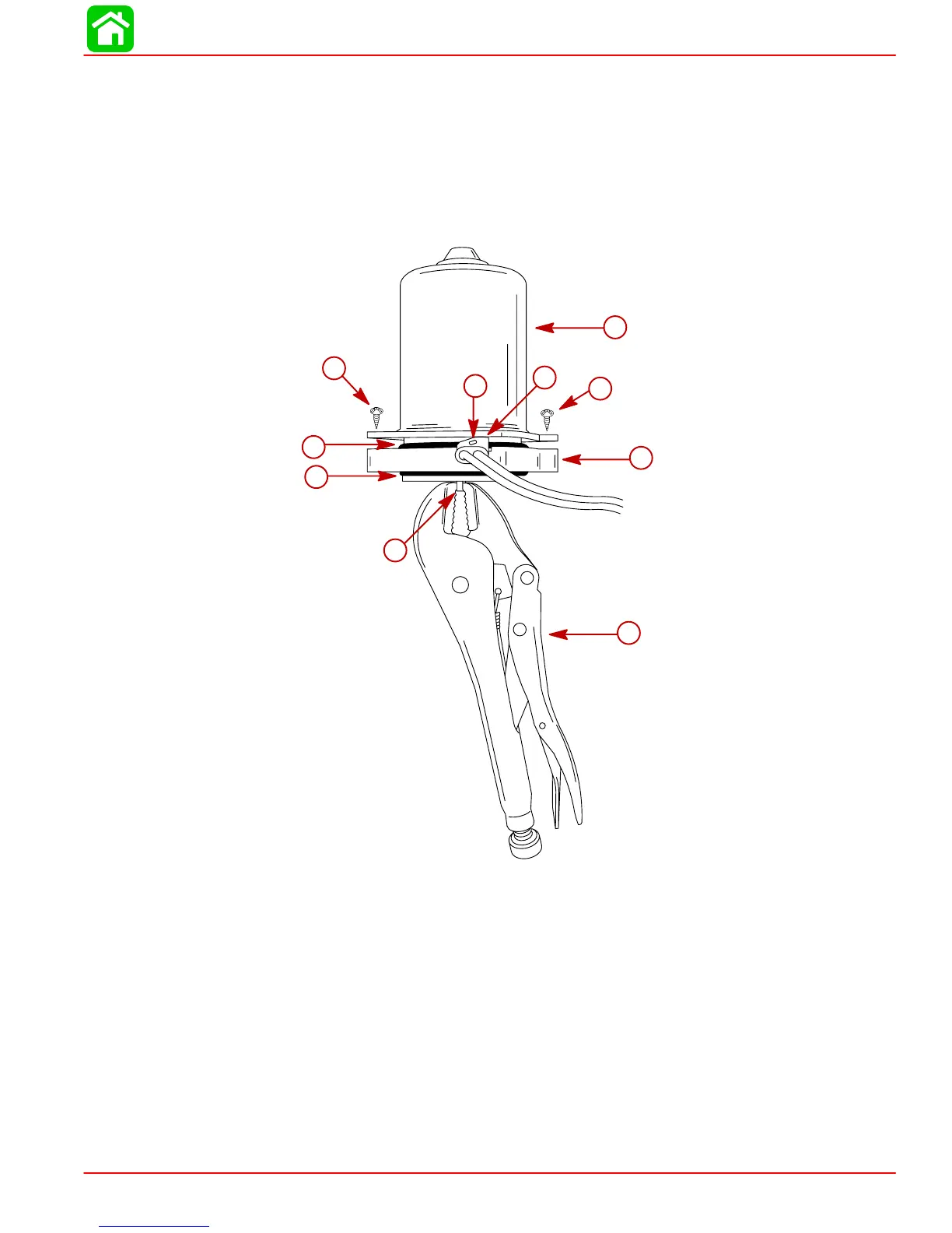
IMPORTANT: Attach Vise Grip pliers to armature shaft before installing frame as-
sembly. The Vise Grip pliers will prevent the armature from being drawn out of the
brush card assembly by the frame magnets while installing the frame assembly.
3. Install Vise Grip pliers on armature shaft.
4. Carefully install frame assembly over armature.
5. Position harness retainer hole over tab in end cap.
6. Secure frame assembly to end cap with 2 screws.
53776
a
b
c
d
e
g
h
i
i
f
a-Vise Grip Pliers
b-Armature Shaft
c-O-ring
d-End Cap
e-Harness Retainer
f-Retainer Hole
g-O-ring
h-Frame Assembly
i-Screws

Table of Contents

Other manuals for Mercury Optimax 115

Questions and Answers:

Question and Answer IconNeed help?

Do you have a question about the Mercury Optimax 115 and is the answer not in the manual?

Mercury Optimax 115 Specifications

General IconGeneral
Fuel Induction System2-stage Direct Fuel Injection (DFI)
Alternator Amp60 amp / 756 watt
SteeringRemote
Cylinders3
StartingElectric
Displacement1.5 L
Bore x Stroke89 x 76 mm
Shaft Length20" (508 mm)
Horsepower115 HP

Related product manuals