POWER TRIM
90-855347R1 JANUARY 1999 Page 5B-23
WARNING
Electrical wires passing through cowl openings must be protected from chafing
or being cut. Follow the recommended procedures outlined in Section 1D of this
Manual. Failure to protect wires as described could result in electrical system fail-
ure and/or injury to occupants of boat.
Testing Power Trim System With Test Gauge Kit (91-52915A6)
IMPORTANT: This test will not locate problems in the trim system. The test will
show if the system is correct after a repair. If minimum pressures are not obtain-
able, the trim system requires additional repair.
“UP” Pressure Check
IMPORTANT: Insure battery is fully charged before performing tests.
1. Tilt outboard to full “Up” position and engage tilt lock lever.
2. Slowly remove “Fill” plug to bleed pressure from reservoir.
3. Remove circlip securing manual release valve and unscrew release valve from trim
assembly.
NOTE: A small amount of trim fluid may drip from manual release valve hole. Place a suit-
able container under trim assembly to collect any leakage.
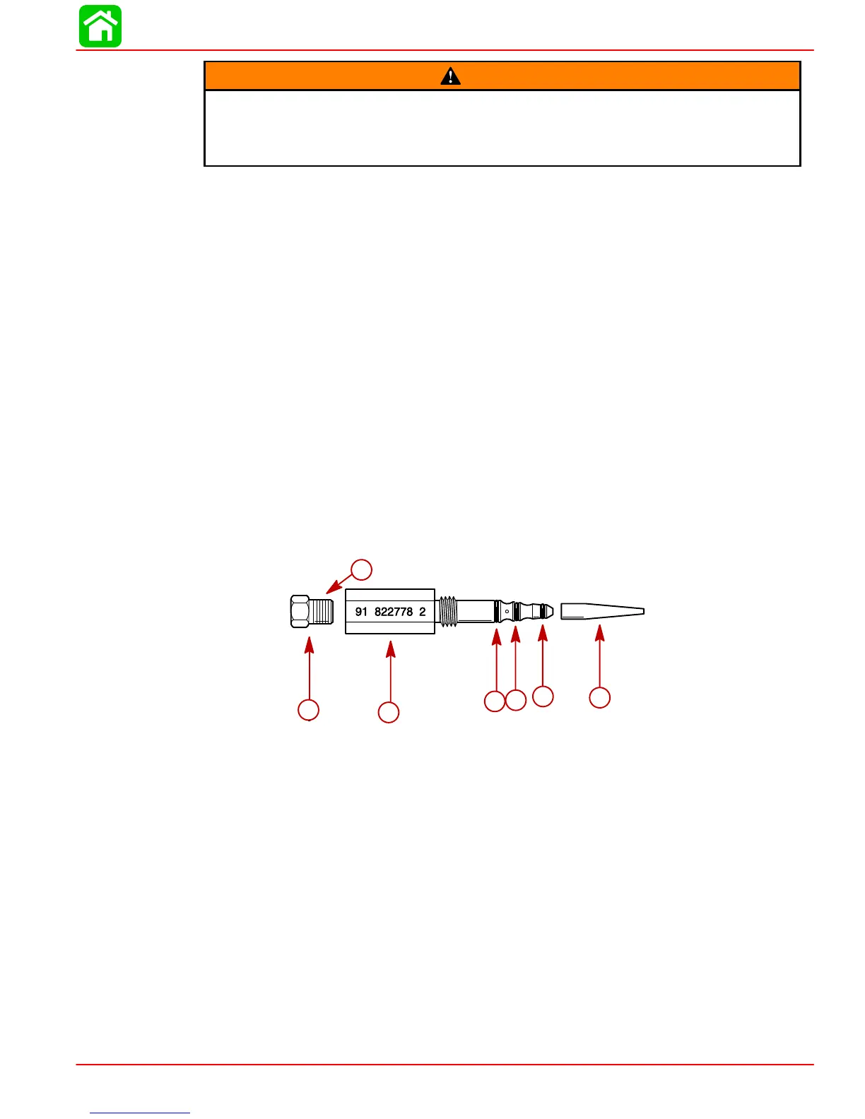
NOTE: Assemble test adaptor by using O-ring installation tool to position small O-ring
onto adaptor 1st, then install medium O-ring and lastly large O-ring. Thread brass fitting
into test adaptor securely using teflon tape on threads.
f
e
d
cb
54457
a
b
c
d
e
f
g
a-Test Adaptor (91-822778A2)
b-O-ring Installation Tool
c-Small O-ring (Install 1st)
d-Medium O-ring (Install 2nd)
e-Large O-ring (Install Last)
f-Brass Fitting
g-Apply Teflon Tape

 Loading...


