POWERHEAD
90-855347R1 JANUARY 1999 Page 4A-13
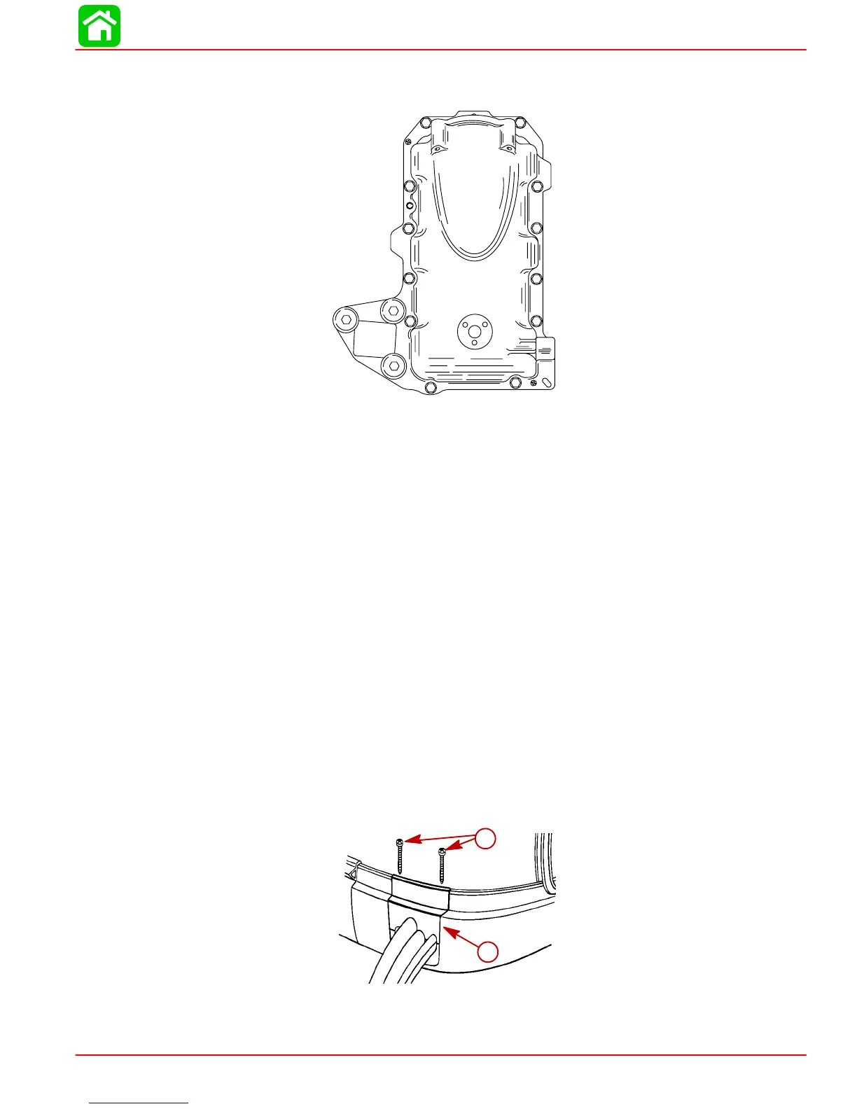
AIR PLENUM/REED BLOCK ASSEMBLY PLATE BOLTS
100 lb. in. (11.3 N·m)
56160
1
2
3
4
5
6
7
8
9
10
11
12
General Information
Powerhead “Disassembly” and “Reassembly” instructions are printed in a sequence that
should be followed to assure best results when removing or replacing powerhead compo-
nents. If complete disassembly is not necessary, start reassembly at point disassembly
was stopped. (Refer to “Table of Contents,” preceding.) Usually, complete disassembly
of powerhead will be required.
If major powerhead repairs are to be performed, remove powerhead from drive shaft
housing. Removal of powerhead is not required for 1) inspection of cylinder walls and pis-
tons (refer to “Powerhead Removal and Disassembly,” following, and remove cylinder
heads and exhaust cover), 2) minor repairs on components, such as ignition system, fuel
injection, reed blocks and cylinder heads and checking operation of thermostats.
Powerhead Removal from Driveshaft Housing
1. Disconnect battery cables from battery terminals.
2. Disconnect fuel tank hose from outboard.
3. Remove top cowling.
4. Remove two screws which secure remote control harness retainer and remove re-
tainer.
52188
a
b
a-Screws
b-Retainer