GENERAL INFORMATION
Page 1C-10 90-855347R1 JANUARY 1999
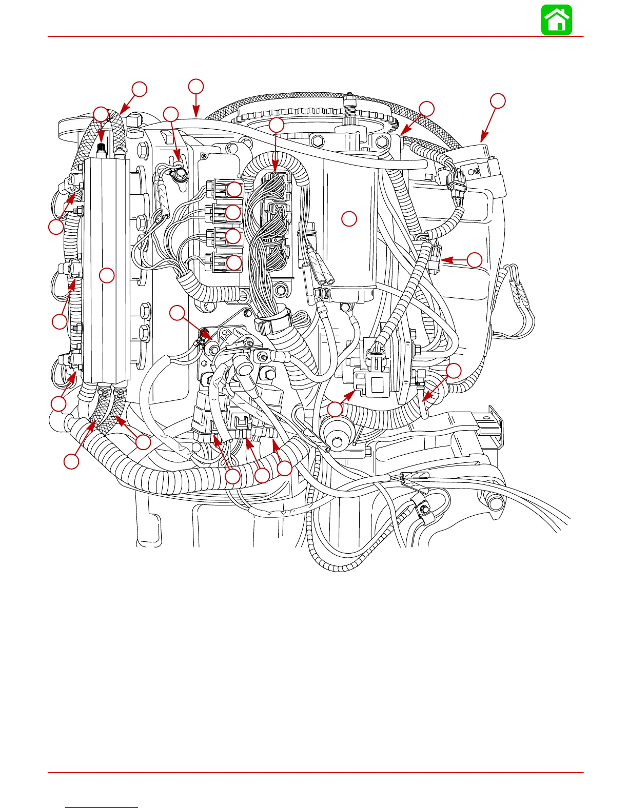
Model 135/150 DFI Powerhead Starboard View
57317
1
2
3
4
5
6
7
8
9
10
11
12
13
14
15
16
17
18
19
20
21
22
23
24
25
1-Fuel Pressure Test Valve
2-Air Compressor Oil Return Line
3-Crank Position Sensor
4-Throttle Plate/Air Plenum Assembly
5-Digital Diagnostic Terminal Connector
6-Oil Hose from Oil Reservoir to Oil Pump
7-Oil Pump
8-Main Power Relay(1998 Model)*
9-Trim DOWN Relay
10 - Trim UP Relay (1998 Model)*
11 - Temperature Sensor
12 - Electronic Control Module
13 - Starter Motor
14 - Starter Solenoid
15 - Oil Pump Fuse
16 - Harness Fuse (20 Ampere)
17 - ECM Fuse (20 Ampere)
18 - Electric Fuel Pump Fuse (20 Ampere)
19 - Air Hose
20 - Starboard Fuel Rail
21 - Fuel Hose
22 - #5 Fuel Injector
23 - #3 Fuel Injector
24 - #1 Fuel Injector
25 - Air Hose from Air Compressor
NOTE: *The location for 1999 Model Main Power Relay and Trim UP Relay are reversed.