EasyManuals Logo

Mercury Optimax 115 User Manual

Mercury Optimax 115
522 pages
To Next Page IconTo Next Page
To Previous Page IconTo Previous Page
Page #172 background imageLoading...
Page #172 background image
DIRECT FUEL INJECTION
Page 3B-24 90-855347R1 JANUARY 1999
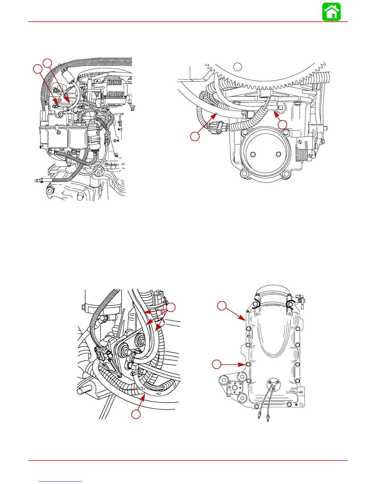
9. Disconnect throttle cam link rod and the Throttle Position Sensor link rod.
10. Disconnect MAP Sensor hose and compressor oil return hose from air management
assembly.
56068
b
a
c
d
b
a
57317
a-Throttle Link Rod
b-Throttle Position Sensor Link Rod
c-MAP Sensor Hose
d-Oil Return Hose
11. Disconnect oil hoses from oil pump.
12. Remove and plug oil inlet hose to oil pump.
13. Remove 12 bolts securing air management assembly to crankcase and remove as-
sembly.
56144
b
a
56140
b
a
a
b
c
d
a-Oil Hoses
b-Oil Inlet Hose
c-Air Management
d-Bolts (12 each)

Table of Contents

Other manuals for Mercury Optimax 115

Questions and Answers:

Question and Answer IconNeed help?

Do you have a question about the Mercury Optimax 115 and is the answer not in the manual?

Mercury Optimax 115 Specifications

General IconGeneral
Fuel Induction System2-stage Direct Fuel Injection (DFI)
Alternator Amp60 amp / 756 watt
SteeringRemote
Cylinders3
StartingElectric
Displacement1.5 L
Bore x Stroke89 x 76 mm
Shaft Length20" (508 mm)
Horsepower115 HP

Related product manuals