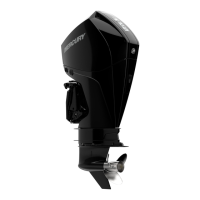
CLAMP/SWIVEL BRACKETS & DRIVE SHAFT HOUSING
90-855347R1 JANUARY 1999 Page 5A-3
Swivel Bracket and Steering Arm
TORQUE
.
NO.
QTY. DESCRIPTION lb-in lb-ft Nm.
1 1 SWIVEL BRACKET ASSEMBLY (BLACK)
2 1 OIL SEAL (LOWER)
3 2 BUSHING
4 1 SPACER
5 1 O-RING
6 2 GREASE FITTING 75 8.5
7 2 BUSHING
8 1 THRUST WASHER
9 2 SCREW (7/16-20 x 7-1/2 IN.)
10 2 MOUNT
11 2 WASHER
12 2 WASHER
13 2 NUT 50 68
14 1 STEERING LINK ASSEMBLY
15 1 SCREW (3/8-24 x 1-1/4 IN.) 20 27
16 2 NUT See Note
17 2 WASHER
18 1 SWIVEL PIN AND STEERING ARM (BLACK)
19 1 BOTTOM YOKE (BLACK)
20 1 RETAINING RING
21 1 BUMPER
22 2 SCREW (1/4-28 x 1/2 IN.) 100 11.5
23 1 TRIM SENDER ASSEMBLY
24 2 SCREW 15 1.7
25 2 LOCKWASHER
26 2 WASHER
27 2 STRIKER PLATE
28 2 LOCKWASHER
29 2 NUT 23 31
30 1 DECAL-Serial Number Overlaminate
NOTE:
A –
Torque nut to 120 lb. in. (13.5 Nm) and then back off 1/4 turn.
NOTE:
B –
Torque nut to 20 lb. ft. (27 Nm)

 Loading...


