POWER TRIM
Page 5B-32 90-855347R1 JANUARY 1999
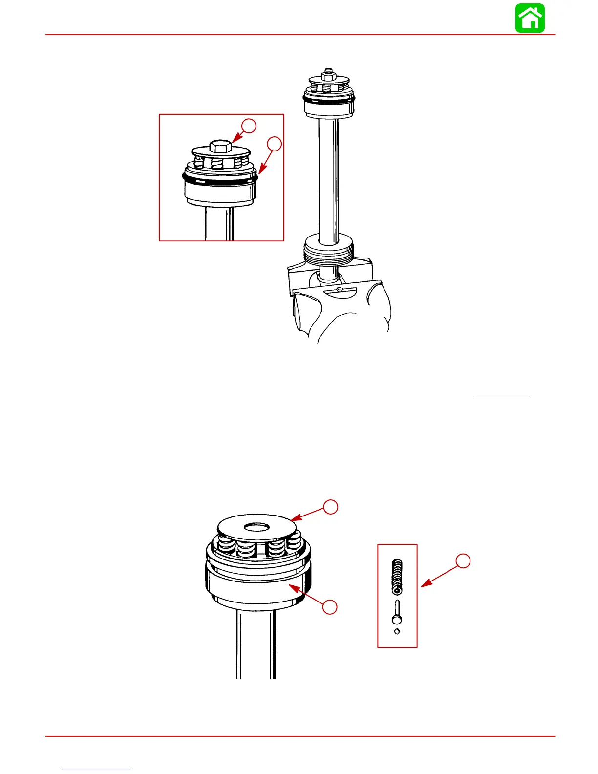
2. Clamp tilt rod in a soft jawed vise. Remove bolt or nut as applicable to disassemble
rod assembly. Remove O-ring.
51378
51340
a
b
a-Bolt (Design 1) or Stud/Nut (Design 2)
b-O-Ring
IMPORTANT: Note Design 1 and 2 on page 5B-31. Design 1 tilt rod assembly
re-
places either tilt rod assembly. Either design will fit as a (replace) cylinder assem-
bly complete.
Design 2 will NOT fit a cylinder originally using a Design 1 tilt rod assembly.
Memory Pistons for Design 1 and 2 differ also and must be used only on the cylin-
der the piston was removed from.
3. Remove washer, check valve assemblies, and piston.
NOTE: Check valve held in by roll pin can be cleaned but not removed.
51363
a
b
c
a-Washer
b-Check Valve Assembly (7)
c-Piston