RIGHT HAND NON-RATCHETING
90-855347R1 JANUARY 1999 Page 6A-35
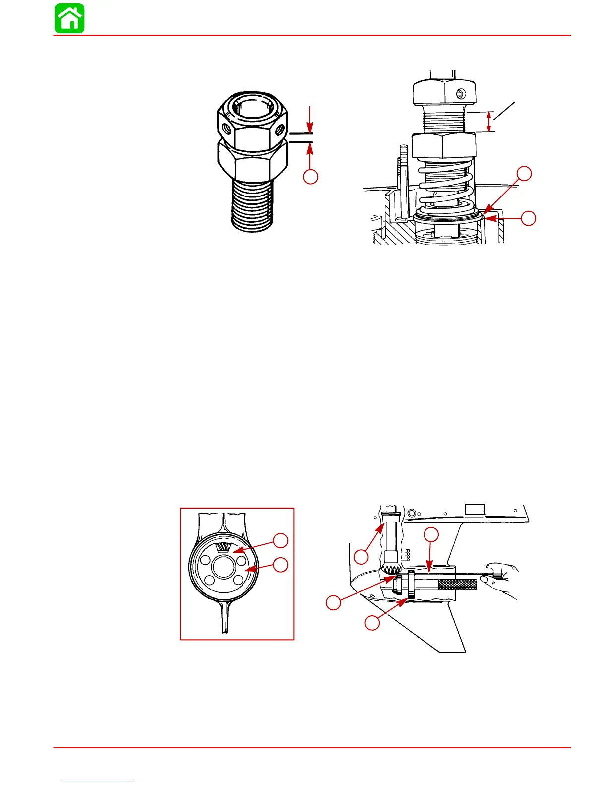
5. Measure distance (a) and increase that distance by 1 in. (25.4 mm) by turning bottom
nut away from top nut.
1 in. (25.4 mm)
51870
b
c
a
a-Distance
b-Adaptor
c-Ledge
6. Turn driveshaft clockwise 2 or more turns to seat driveshaft bearings.
7. Insert Pinion Gear Locating Tool* (91-74776) into gear housing until it bottoms out on
bearing carrier shoulder.
*Pinion Gear Locating Tool (91-12349A2) can be used. Use flat #7 and disc #2. Follow
instructions supplied with tool.
8. Determine pinion gear depth by inserting a feeler gauge thru access slot in pinion gear
shimming tool.
9. Clearance between shimming tool and pinion gear should be 0.025 in. (0.64 mm).
10. If clearance is correct, leave Bearing Preload Tool on driveshaft for “Determining For-
ward Gear Backlash,” following.
11. If clearance is not correct, add (or subtract) shims at location shown to raise (or lower)
pinion gear. When reinstalling pinion nut, apply Loctite 271 on threads of nut and re-
torque pinion nut.
24643
a
b
c
d
c
a
a-Pinion Gear Tool (91-74776 or 91-12349A2)
b-Feeler Gauge
c-Obtain 0.025
in. (0.64 mm) Clearance between Shimming Tool and
Pinion Gear
d-Add or Subtract Shim(s) Here
 Loading...


