LEFT HAND NON-RATCHETING
90-855347R1 JANUARY 1999 Page 6B-13
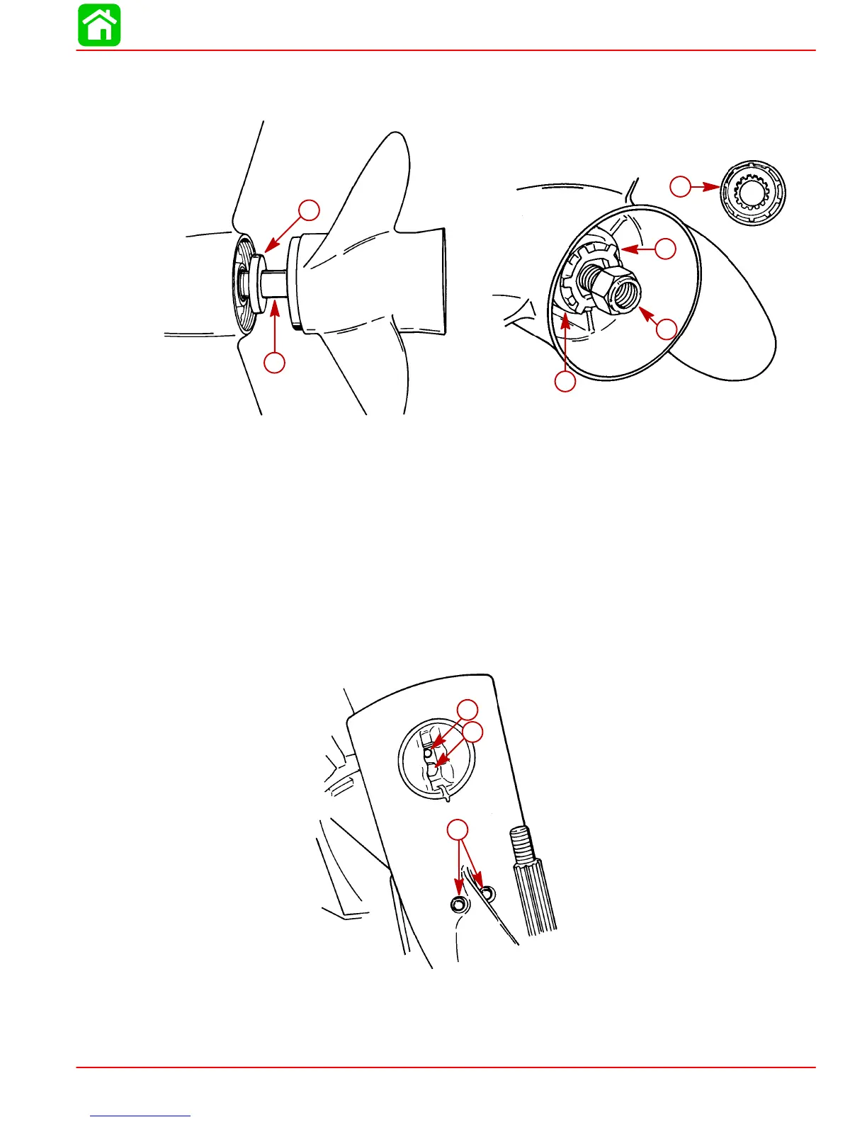
4. Bend tabs of propeller tab washer away from thrust hub (rear), then remove propeller
locknut, tab washer, thrust hub (rear), propeller and thrust hub (forward) from propel-
ler shaft.
51916
51912
a
b
c
d
e
f
a-Thrust Hub (Forward)
b-Propeller Shaft
c-Continuity Washer (If Equipped)
d-Rear Thrust Hub
e-Tab Washer
f-Propeller Nut
5. Mark gear housing and trim tab so that trim tab can be reinstalled in the same position.
Remove plastic cap at rear edge of driveshaft housing. Remove bolt that secures trim
tab and remove tab from gear housing.
6. Once trim tab is removed, remove bolt from inside of trim tab cavity.
7. Remove 2 locknuts from bottom middle of anti-cavitation plate.
51866
a
b
c
a-Bolt (Secures Trim Tab)
b-Bolt (Inside Trim Tab Cavity)
c-Locknuts and Washers
 Loading...


