ATTACHMENTS / CONTROL LINKAGE
90-855347R1 JANUARY 1999 Page 7-15
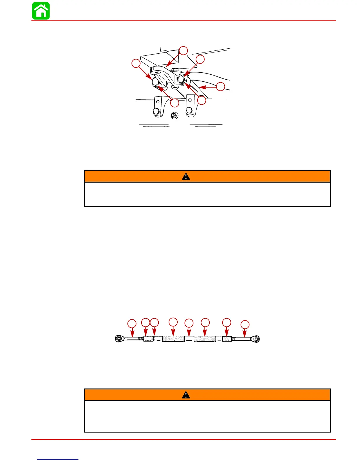
STEERING ARM EXTENSION BRACKET INSTALLATION
Secure a steering arm extension bracket to each out- board’s steering arm.
51889
a
b
c
c
d
d
a-Steering Arm (Port Outboard Shown)
b-Extension Bracket
c-Locking Retainer (2 Each Bracket)
d-Bolts (2 Each Bracket) 1-1/4 in. (31.8 mm) Long - Torque to 23 lb. ft. (31 Nm),
Then Bend Corner Tabs of Locking Retainers Up Against Flats on Each Bolt
WARNING
Locking retainer corner tabs MUST BE bent up and against flats on each bolt that
secures extension bracket to outboard steering arm to prevent bolts from turning
out.
STEERING COUPLER ASSEMBLY AND INSTALLATION
Position outboards so that they are facing straight forward. (Distance between threaded
hole centers of steering arm extensions MUST BE equal to distance between propeller
shaft centerlines.)
Lubricate inside of rubber sleeves with 2-4-C w/Teflon and slide sleeves on steering cou-
pler.
Work rubber bushings onto threaded ends of steering eyes.
Thread jam nut on starboard steering eye.
Thread steering eyes equally into coupler, so that distance between hole centers of steer-
ing eye ball joints is equal to distance between threaded hole centers of steering arm ex-
tensions. Exposed threads of steering eyes MUST BE of equal length and threads MUST
NOT extend out from coupler more than 2-3/4 in. (70 mm).
50061
c
d
e
b
a
b d
c
a-Coupler
b-Rubber Sleeve
c-Steering Eye
d-Rubber Bushing
e-Jam Nut
WARNING
Both steering eyes must be threaded into coupler 3/4 in. (19 mm) minimum.
Thread length of steering eye is 3-1/2 in. (89 mm), so exposed thread must not
extend out of coupler more than 2-3/4 in. (70 mm). Failure to adhere to this re-
quirement could result in steering system failure.
 Loading...


