CHARGING & STARTING SYSTEM
90-855347R1 JANUARY 1999 Page 2B-17
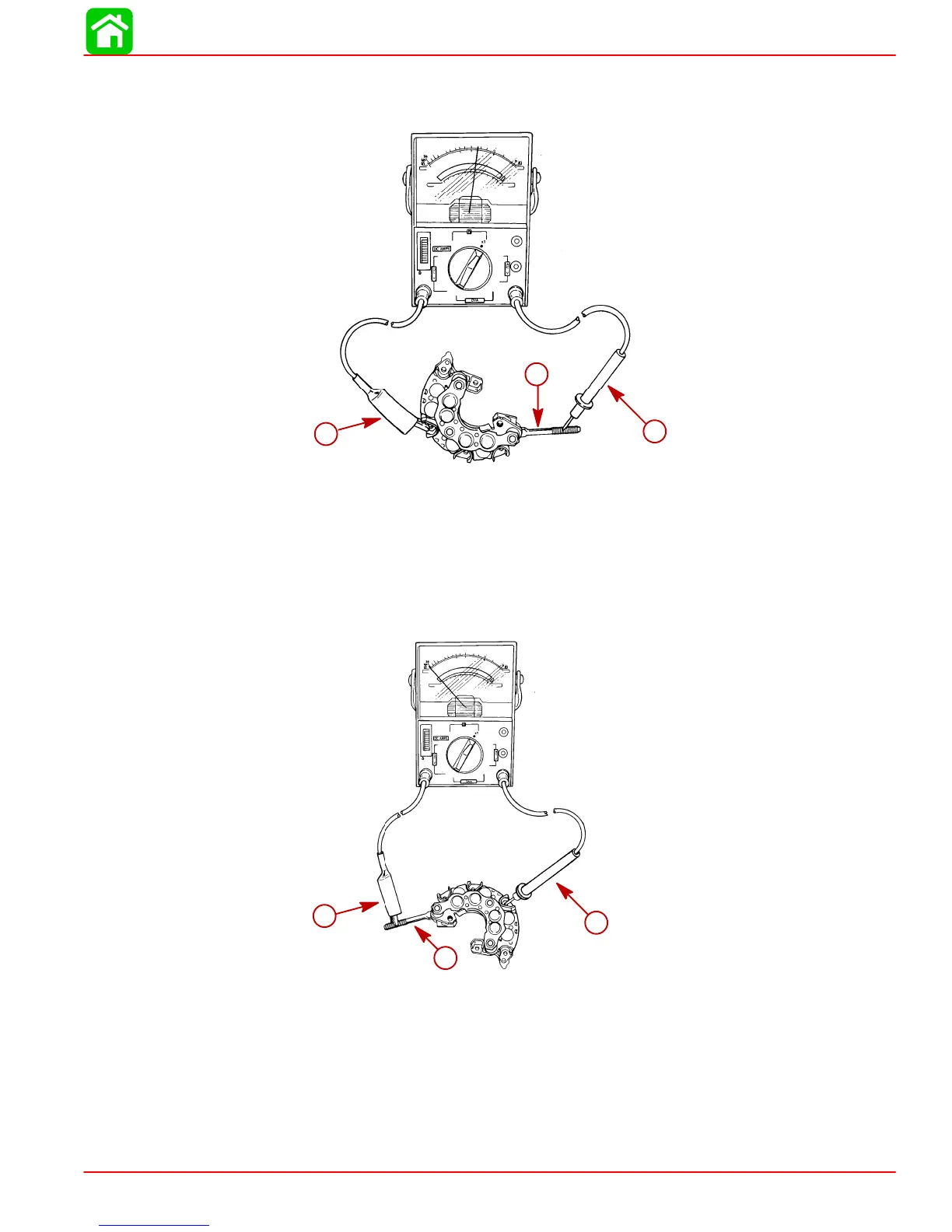
NOTE: To test rectifier assembly, touch POSITIVE (+) lead from ohmmeter to POSITIVE
stud and NEGATIVE (–) lead from ohmmeter to each diode terminal. The ohmmeter
should indicate continuity.
51679
b
a
c
a
b
c
a-Positive Stud
b-Positive Ohm Lead
c-Negative Ohm Lead
Reverse leads – NEGATIVE lead on POSITIVE stud and POSITIVE lead on each diode
assembly. NO CONTINUITY should be observed. If continuity is observed in both tests,
or NO CONTINUITY is observed in both tests, the rectifier assembly is defective and must
be replaced. Torque rectifier screws to 17 lb-in (1.9 Nm).
51679
b
a
c
a
b
c
a-Positive Stud
b-Negative Ohm Lead
c-Positive Ohm Lead
IMPORTANT: Depending on the polarity of the ohmmeter, reversed readings may
be obtained – I.E. – CONTINUITY is observed when the NEGATIVE lead touches the
POSITIVE stud and NO CONTINUITY is observed when the POSITIVE lead touches
the POSITIVE stud.
 Loading...


