4 - COMMANDS AND INSTRUMENTS
4 - 24
The attachment installed on your machine was correctly identified by the system, but the
corresponding image is not available in the database.
Make sure that selector (204) is turned to the AUTO position
The attachment installed on your machine is either not equipped with a self-identification
sensor, or it was not automatically identified by the system due to a system failure or
malfunctioning. Manual selection of the type of attachment installed with selector (204) was
necessary.
When selector switch (204) is in the AUTO position, mode “C” of the load chart is active,
referring to attachments whose centre of gravity is 4 metres ahead of the carriage.
The attachment installed on your machine is either not equipped with a self-identification
sensor, or it was not automatically identified by the system due to a system failure or
malfunctioning. Manual selection of the type of attachment installed with selector (204) was
necessary.
When selector switch (204) is in the 0.5/0.6 position, mode “A” of the load chart is active,
referring to attachments whose centre of gravity is between 0.5 and 0.6 metres ahead of the
carriage.
The attachment installed on your machine is either not equipped with a self-identification
sensor, or it was not automatically identified by the system due to a system failure or
malfunctioning. Manual selection of the type of attachment installed with selector (204) was
necessary.
When selector switch (204) is in the 1.5 position, mode “B” of the load chart is active, referring
to attachments whose centre of gravity is no more than 1.5 metres ahead of the carriage.
The attachment installed on your machine is either not equipped with a self-identification
sensor, or it was not automatically identified by the system due to a system failure or
malfunctioning. Manual selection of the type of attachment installed with selector (204) was
necessary.
When selector switch (204) is in position 4, mode “C” of the load chart is active, referring to
attachments whose centre of gravity is no more than 4 metres ahead of the carriage.
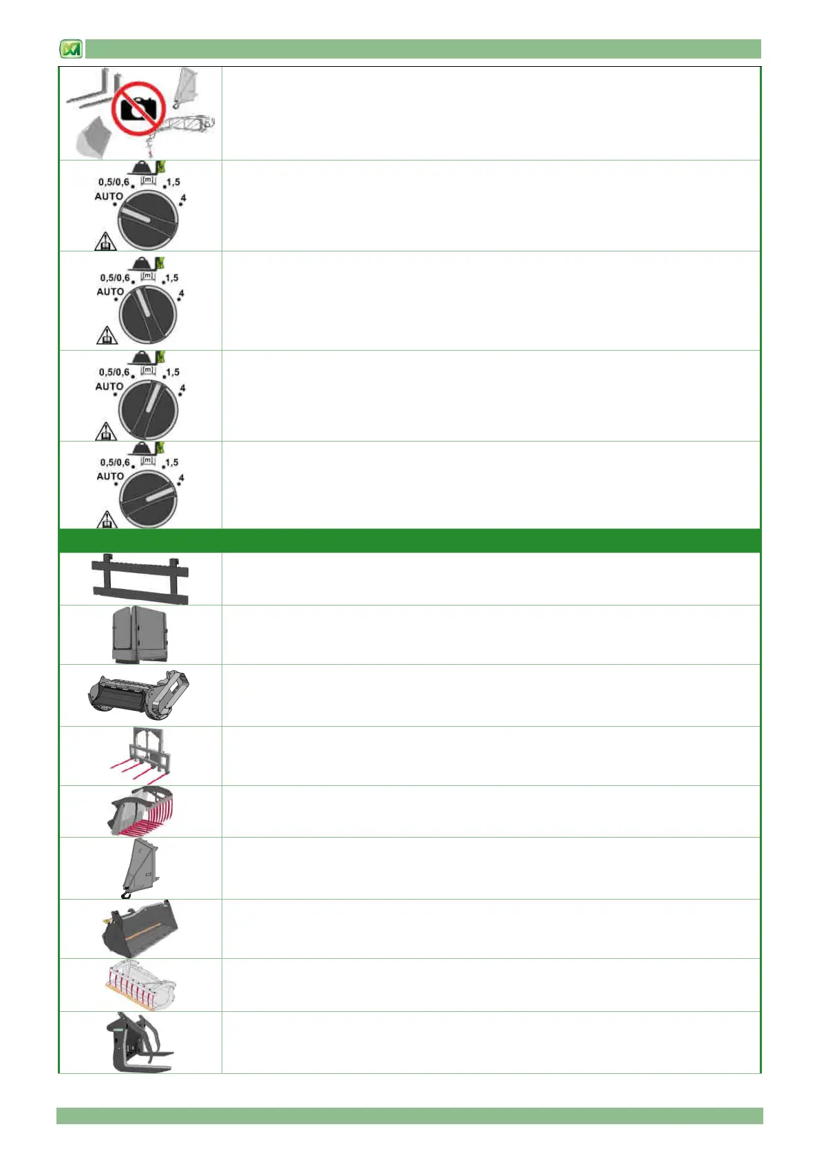
Attachments whose centre of load gravity is 0.5/0.6 metres from the machine carriage (position “A” of selector 204)
The TRAVELLING LIFT ON CARRIAGE - SIDE-SWINGING CARRIAGE /
CARRIAGE WITH FLOATING FORKS - FEM CARRIAGE / EXTRA-LARGE FORK CARRIAGE
attachment, installed on the machine, was correctly identified by the system.
The BRICK HANDLER attachment installed on the machine was correctly identified by the
system.
The CHOPPER attachment installed on the machine was correctly identified by the system.
The HAY BALE HANDLER WITH GRABS / 2/3 FOLDING-SPIKE FORK FOR HAY BALES /
HAY BALE FORK WITH SLIDING PROTECTION attachment, installed on the machine, was
correctly identified by the system.
The MANURE FORK WITH GRABS attachment installed on the machine was correctly
identified by the system.
The CARRIAGE-MOUNTED HOOK attachment installed on the machine was correctly
identified by the system.
The 4 IN 1 BUCKET attachment installed on the machine was correctly identified by the
system.
The MULTI-PURPOSE LOADER WITH CLAW attachment installed on the machine was
correctly identified by the system.
The DOUBLE LOG GRABS attachment installed on the machine was correctly identified by the
system.