Disassemble the Assemblies Repair and Disassembly
6 - 34 046-006272-00 A7™ Service Manual
FIGURE 6-67
6.2.3.9 Remove the Cylinder Bracket Assembly
1. Open the service door and refer to“Open the Service Door” on page 6-3..
2. Remove the rear panel and refer to “Remove the Rear Cover Plate Assembly” on page 6-29..
3. Remove the module rack cabinet assembly and refer to “Remove the Module Rack Assembly” on
page 6-47.
4. Remove the module rack bracket assembly and refer to “Remove the Module Rack Fan” on
page 6-48.
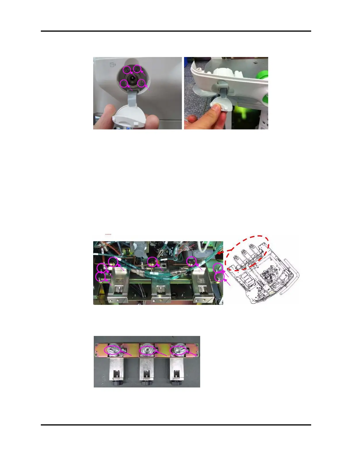
5. Unplug the tubes from the cylinder bracket assembly.
6. Remove the copper pipe from cylinder bracket assembly.
7. Unscrew the four screws on the cylinder bracket to remove the assembly.
FIGURE 6-68
8. Unscrew the four screws on the cylinder bracket to remove O2, N2O and AIR cylinder bracket
assemblies.
FIGURE 6-69