EasyManuals Logo

Mindray A7 Service Manual

Mindray A7
482 pages
To Next Page IconTo Next Page
To Previous Page IconTo Previous Page
Page #397 background imageLoading...
Page #397 background image
A7™ Service Manual 046-006272-00 6 - 39
Repair and Disassembly Disassemble the Assemblies
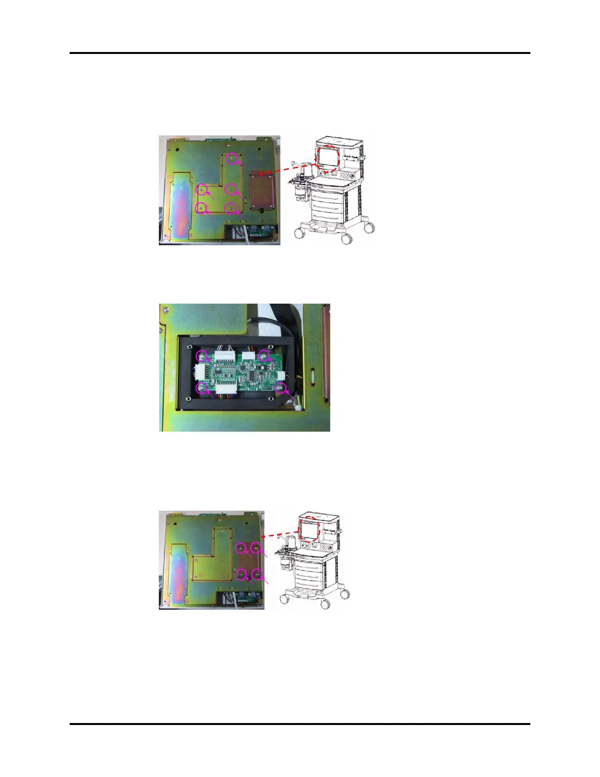
6.2.5.2 Remove the Display Adaptation Board
1. Remove display assembly and refer to “Disassemble the Auxiliary Work Surface” on page 6-36..
2. Unscrew the five screws on the cover plate of the display mount.
FIGURE 6-80
3. Unplug the related cables from the display interface board.
4. Unscrew the four screws on the display interface board and remove the board.
FIGURE 6-81
6.2.5.3 Remove the Touch Screen Control Board
1. Remove display assembly.
2. Unscrew the four screws and the cover plate of the touch screen control board.
FIGURE 6-82
3. Unplug the related cables from the touch screen control board.

Table of Contents

Other manuals for Mindray A7

Questions and Answers:

Question and Answer IconNeed help?

Do you have a question about the Mindray A7 and is the answer not in the manual?

Mindray A7 Specifications

General IconGeneral
TypeAnesthesia Workstation
BrandMindray
ModelA7
Display15-inch color touchscreen
Oxygen FlushYes
Gas InletsO2, N2O, Air
Ventilation ModesSIMV, PSV
Breathing SystemIntegrated
Gas MonitoringO2, CO2, N2O
Monitoring ParametersFiO2
CO2 MonitoringMainstream or Sidestream
Power Supply100-240 V, 50/60 Hz

Related product manuals