Introduction Replacement Parts
7 - 8 046-006272-00 A7™ Service Manual
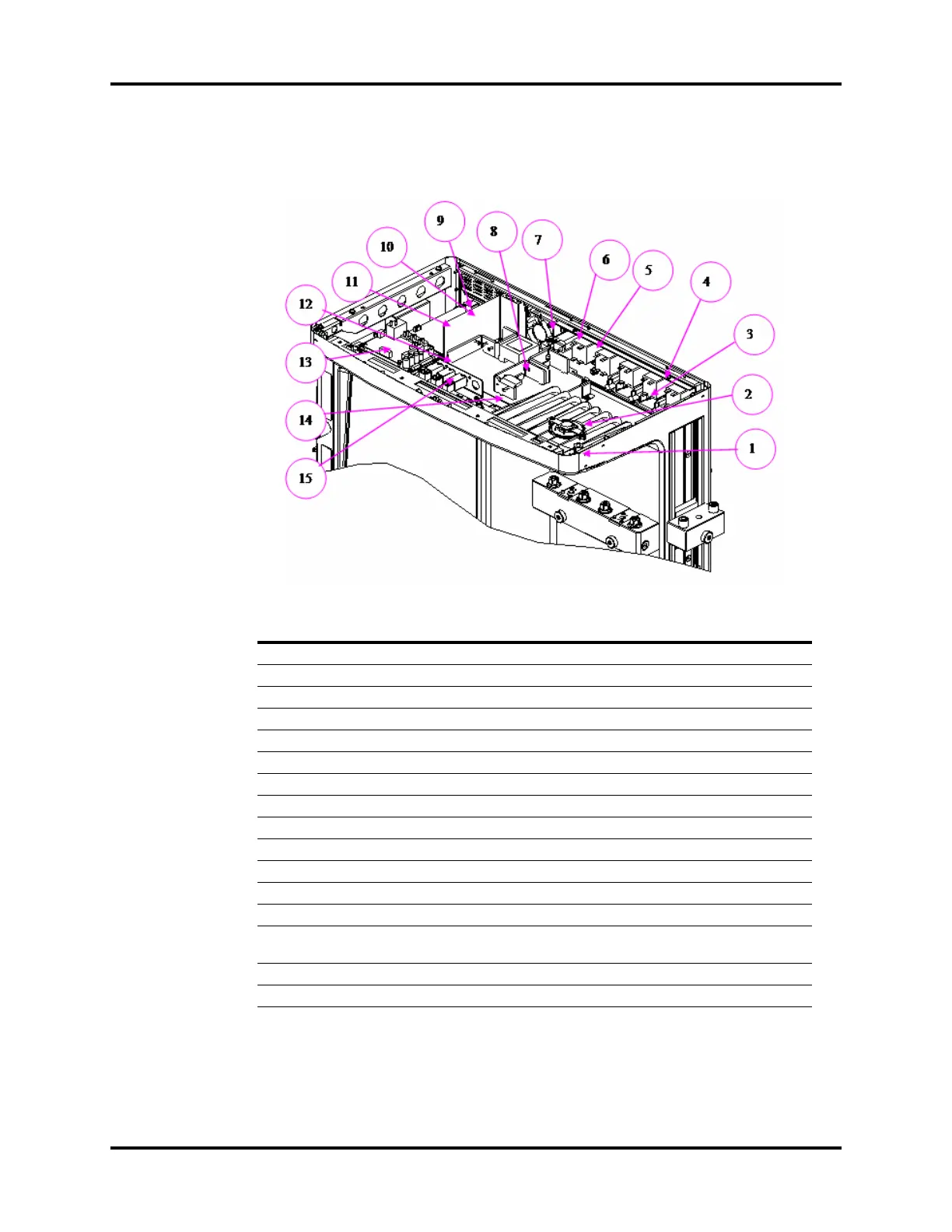
7.1.2.3 A7 Hardware Box
NOTE: Follow the two steps below to install the VGA output.
1.Replace the CPU board (PN: 115-040636-00), the monther board (PN:
051-002662-00), and the output bracket of the mother borad (PN:115-
040634-00).
2.Upgrade the software (software bundle version 02.11.00 and later).
FIG.NO. DESCRIPTION PART NUMBER
1 Top lighting board PCBA 801-0631-00039-00
2 Speaker and connecting cable 801-0631-00038-00
3 American-standard auxiliary electrical outlet 801-0631-00032-00
4 Breaker (3.0 A) 801-0631-00031-00
5 Breaker (10.0 A) 801-0631-00030-00
6 10 A filter power panel mount 801-0631-00029-00
7 Fan 801-0631-00028-00
8 Power board (A7) 115-018145-00
9 Wind shield 042-009056-00
10 Button cell Lithium 3V35mAh D12.5*2.0 M05-010R03---
11 A7 CPU board 115-040636-00
12 Battery interface board PCBA 801-0631-00109-00
13 Ventilator control board 801-0631-00027-00
14 Mother board PCBA (A7)
051-001259-00
051-002662-00 (VGA)
15 3-way valve assembly 801-0631-00146-00
/ Fuse on power board 010-000087-00