3. Product presentation
MiR500 User guide (en) 09/2019 - v.1.3 ©Copyright 2018-2020: Mobile Industrial Robots A/S. 31
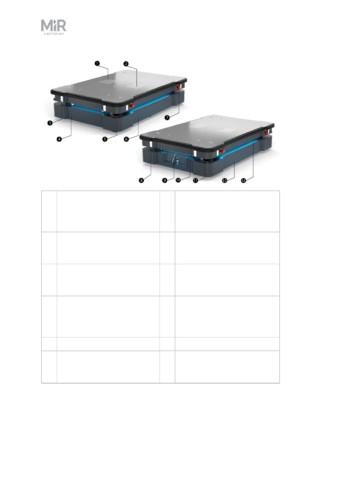
1. Left cover plate: access to power
interface, GPIO interface and
Ethernet interface
8. Proximity sensors: eight pcs., two
in each corner behind corner
cover (see Sensor system on
page51)
2. Right cover plate: access to safety
interfaces Aux. safety functions
and Aux. Emergency stop
9. 3D depth cameras: two pcs.,
detect objects in front of the robot
(see Sensor system on page51)
3. Signal light: eight pcs., two on
each corner (see Sensor system
on page51)
10. Front maintenance hatch: opens to
front compartment (see MiR500
internal parts on page36)
4. Rear maintenance hatch: opens
to rear compartment (see
MiR500 internal parts on
page36)
11. Front safety laser scanner (see
Sensor system on page51)
5. Rear safety laser scanner 12. Left-hand side maintenance hatch
6. Right-hand side maintenance
hatch
13. Status light: on all four sides of the
robot (see Sensor system on
page51)