Chapter 4 Mx-Series Unit Description 4-
17
The head assembly attached to the gantry can place up to 6 chip-type
components or small leaded components at a time. See <Table 4-7~11>
for applicable component sizes and types.
Once the head assembly configuration and the number and type of
components that can be placed at a time are defined, the number and
type of upward cameras (module camera, precision camera, CSP
camera) to be used for component recognition are determined
accordingly. One 3-module camera is used for one 6-module head.
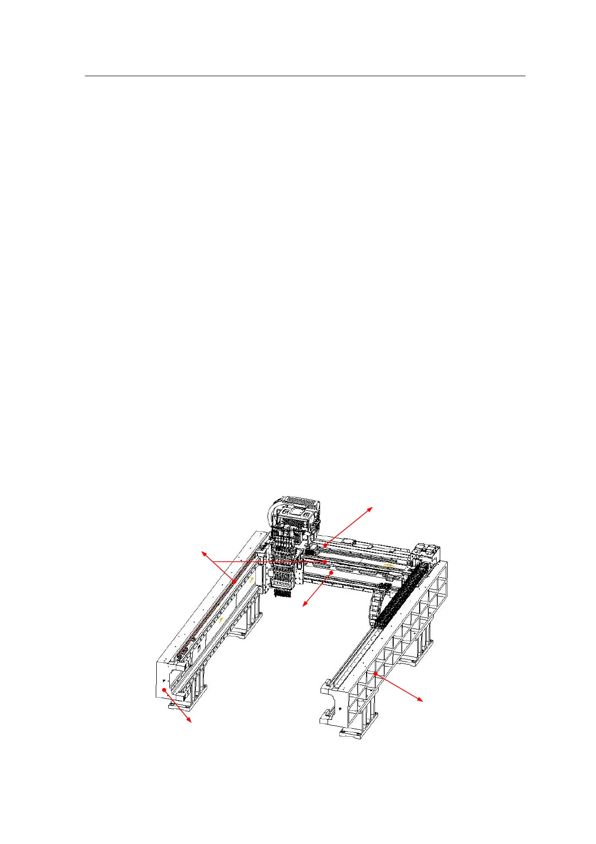
XY gantry
• Structure
As seen in <Figure 4-10>, the XY gantry consists of one X-axis frame
moving along two Yaxis frames.
Each axis is driven by a high-speed linear motor and is equipped with an
optical linear encoder to recognize the axial position.
<Figure4-10 Mx-Series XY-gantry>