Installation
152
Mitel 470 as of R4.1
syd-0585/1.2 – R4.1 – 08.2016
Fig. 66 Front panel, EFOP fan-out-panel
In the following, these analogue phones are referred to as emergency phones. In nor-
mal operation emergency phones act like ordinary internal phones. Only phones capa-
ble of operating without their own power supply are suitable as emergency phones.
Both DTMF and pulse dialling phones are supported. It is recommended to identify
emergency phones as such.
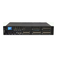
The fan-out panel EFOP takes up the space of one height unit in a rack and can be fit-
ted directly above or below the communication server.
Detailed Description
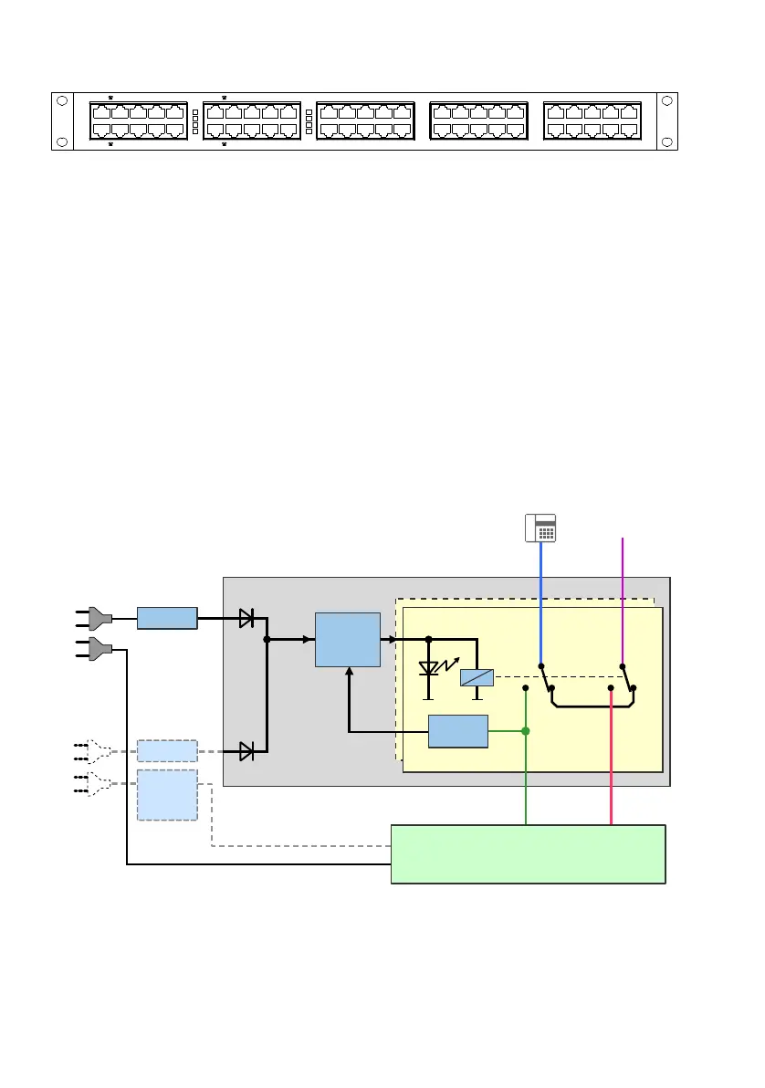
The block diagram below illustrates how the EFOP fan-out-panel operates. The lines
are switched over by relays. When relays are in a de-energised idle state, the emer-
gency phones are connected directly with the analogue exchange lines (PSTN). For
each port the relay switching status is indicated by an LED.
[1] relevant only with APS2 auxiliary power supply unit in redundancy operation
Fig. 67 Block diagram, EFOP fan-out-panel
3671
);6
3671
);2
3671
);6
3671
);2
[1]
FXO
FXS
1 … 8
1 … 8
Voltage
detection
AC / DC
Control
AC / DC
1 … 8
1 … 8
1 … 8
EFOP
115/230 VAC
115/230 VAC
Auxiliary
power suply
unit (APS2)
Mains power 2
Mains power 1
PSTN
Communication server