Operation and Maintenance
220
Mitel 470 as of R4.1
syd-0585/1.2 – R4.1 – 08.2016
6. 4. 3. 5 Display of event messages
If an event message occurs in normal operation, the LED pattern switches from "slowly
flashing green" to "slowly flashing orange-green" and the event message is indicated
on the colour display.
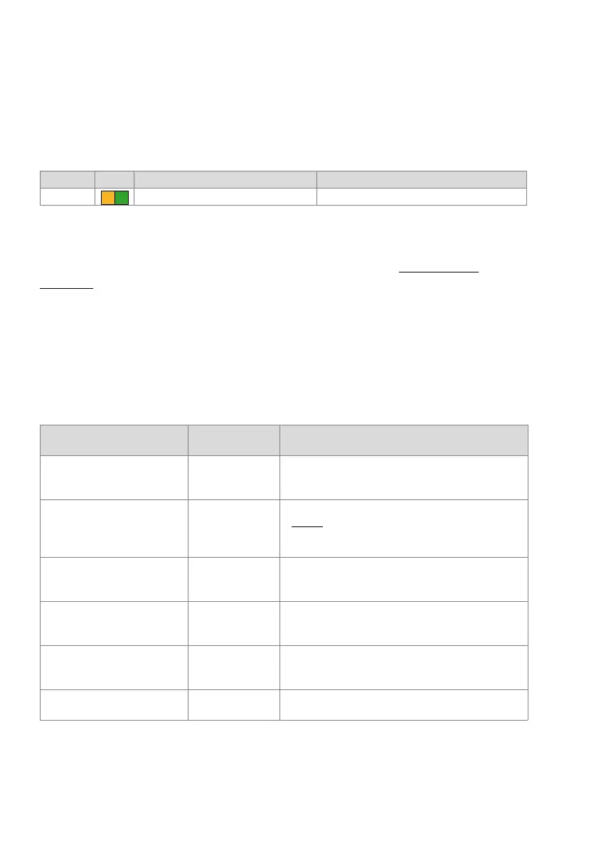
Tab. 96 Display of event messages in normal operation:
6. 4. 3. 6 Status LEDs on Ethernet interfaces
For explanations of the status LEDs on Ethernet interfaces see "Status LED",
page 158.
6. 4. 4 Colour display
The colour display has different display modes, which depend in part on the Call Man-
ager's operating mode.
The table below summarises the display modes.
Tab. 97 Operating modes and display priorities
Pattern LED Duration Meaning
11 As long as the event message exists Event message present
Display mode of the colour dis-
play
Call Manager
operating mode
Trigger event and purpose
Error mode
(Error mode)
System setup 2 • Triggered by software or hardware error.
• The error is shown on the display.
• The system is unable to run.
Boot menu
(Boot command mode)
System setup 2 • Is shown during the start-up phase 2 (LED pattern5 in
Tab. 93
) for approx. 3 seconds.
• Allows the user to reset the IP address data or to carry
out a first start.
Menu mode
(Application command mode)
Normal operation • Triggered by pressing any navigation key briefly in the
traffic load mode.
• Allows the user to run various advanced functions.
Traffic load mode
(Traffic mode)
Normal operation • After the startup of the Call Manager or after exiting the
menu, idle or event message mode.
• Shows the current traffic load of the Call Manager.
Idle mode
(Idle mode)
Normal operation • After a certain amount of time without user interaction
from the traffic mode or the event message mode.
• Screen saver and energy saving function.
Event message mode
(Event message mode)
Normal operation • After one or more event messages are received.