Installation
93
Mitel 470 as of R4.1
syd-0585/1.2 – R4.1 – 08.2016
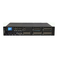
4. 2 Fitting the communication server
The Mitel 470 communication server is designed for installation in a 19” rack (2 height
units). The communication server can also simply be placed on a flat surface. Wall-
mounting is not allowed.
4. 2. 1 Equipment supplied
The equipment supplied with the Mitel 470 includes:
• Mitel 470 communications server with integrated Call Manager card
• Fastening kit for rack mounting
• 2 covers for the rack screws
• 4 rubber feet for desktop installation
•Power cord
• Product information
4. 2. 2 Location requirements
The following location requirements must be observed when positioning the communi-
cation server.
Hazard
Failure to observe the location requirements can cause the communication server to overheat,
damaging electrical components and/or the surrounding area.
An event message is generated if the heat dissipation is insufficient. Appropriate measures
must then be taken immediately to improve heat dissipation, e.g. providing the required clear-
ances or lowering the ambient temperature.
Tab. 39 Mitel 470 Location requirements
Heat radiation • Do not position in direct sunlight, near radiators or near other heating sources
EMC • Do not position in strong electromagnetic fields of radiation
(e.g.near x-ray equipment, welding equipment or similar).
Heat dissipation • With desktop and rack mounting the ventilation holes (left) and the fan outlet (rear) must not be
obstructed.
• All the communication server’s housing openings must always be closed during operation to
ensure a controlled flow of air (see Fig. 18
).
Environment • Ambient temperature 5 °C...45 °C
• Relative humidity 30…80%, non-condensing