Expansion Stages and System Capacity
42
Mitel 470 as of R4.1
syd-0585/1.2 – R4.1 – 08.2016
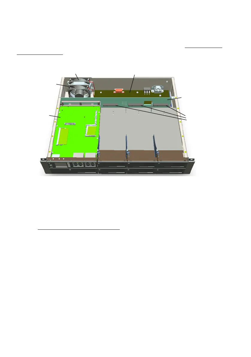
For a clearer overview the figure below shows the open communications server from
above with an additional fan fitted. The housing cover is in two parts. The upper, rear
cover must be removed for the purpose of fitting an additional fan (see "Fitting an addi-
tional fan", page 97 for the procedure).
Fig. 7 Mitel 470 basic system fitted with a redundant fan unit
3. 2. 1 Interfaces, display and control elements
The interfaces accessible from the outside are located on the front and rear side of the
basic system. The housing cover only needs to be opened when fitting an additional
fan (see "Fitting an additional fan", page 97
).
Basic system (without call manager card)
The figure below shows the positions of basic system interfaces without call manager
card.
Plug-in connections
for the interface
cards
Backplane (BP2U)
Internal power supply
unit (PSU2U)
Call Manager card
(CPU1)
Standard fan (tted)
Redundant fan
unit as an option
(RFU)