Expansion Stages and System Capacity
43
Mitel 470 as of R4.1
syd-0585/1.2 – R4.1 – 08.2016
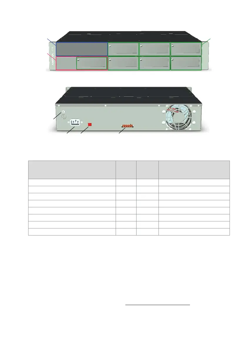
Fig. 8 Position of the interfaces on the basic system
Tab. 14 Interfaces of the basic system
Call Manager card CPU1
The call manager card is the core the basic system and already fitted on delivery. Be-
sides a powerful processor it also comprises a RAM module, a Flash memory card with
the call manager software and an EIM card, on which the licences among others are
stored.
The call manager card comprises two powerful DSP chips, one of which can be as-
signed selectable functions. Two DSP modules can also be fitted as an option to fur-
ther boost the media resources (see also "Media resources", page 48
).
Interfaces
Number
of
entries
Position Remarks
Slot for Call Manager card CPU1 1 [1] Device ships already equipped
Slot for application card CPU2 1 [2] Can be fitted as an option
Slots for interface cards 7
1)
1) 1 fewer slot if CPU2 application card is fitted
[3] Can be fitted as an option
Interface for redundant fan unit 1 Connectors inside the housing
Earth connection 1 [4]
Mains socket for 115/230 V power supply input 1 [5]
115/230 V voltage converter 1 [6]
Socket for auxiliary power supply unit APS2 1 [7]