Installation
113
Mitel 470 as of R4.1
syd-0585/1.2 – R4.1 – 08.2016
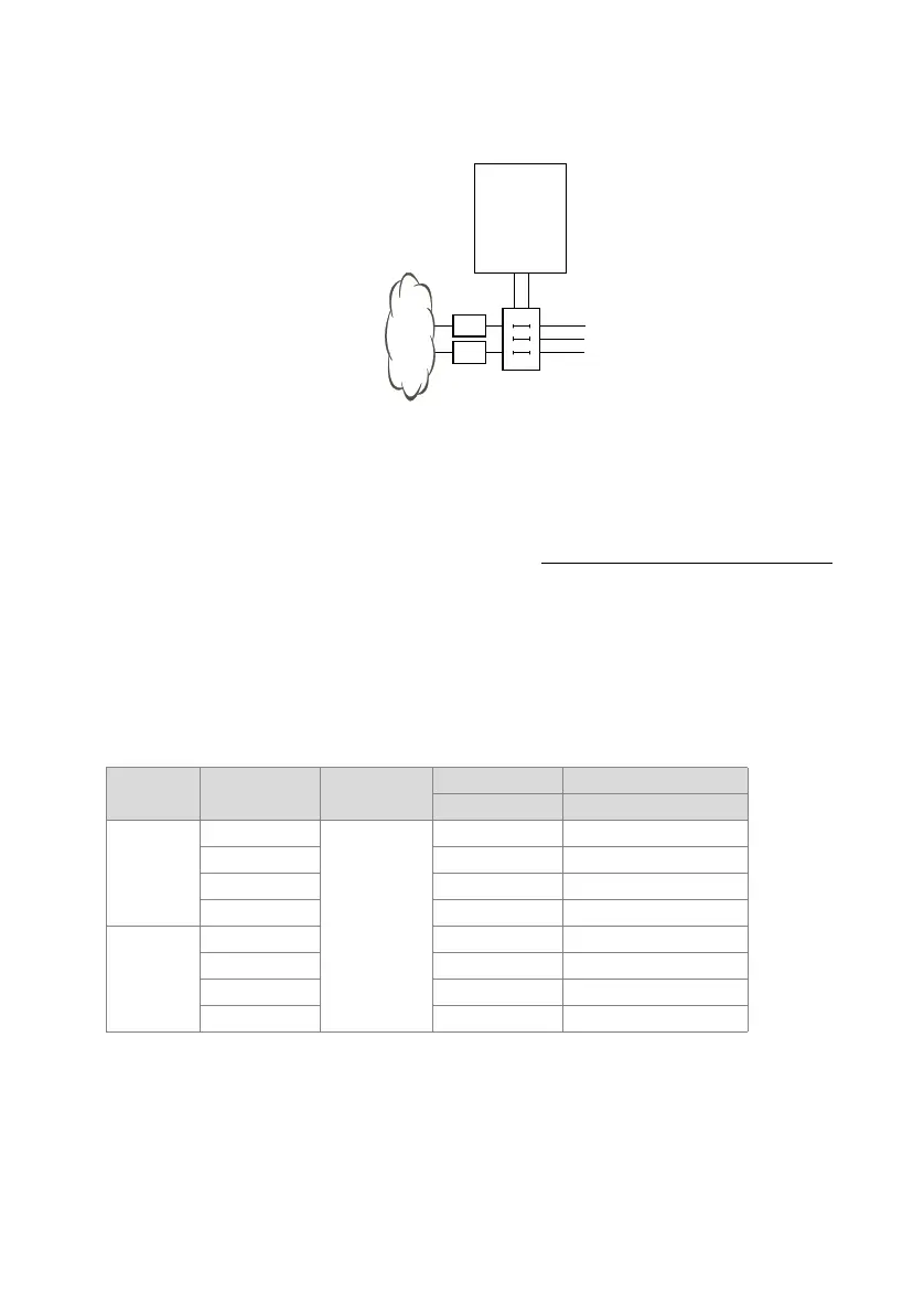
4. 6. 2. 1 Connection via main distribution board
Fig. 30 Connection via main distribution board
The interface sockets on the front panel and on the fan-out-panel (FOP) where applica-
ble are connected with the (main) distribution frame or the patch panels using either
patch cables or prefabricated system cables (see "Equipment Overview", page 254
).
Prefabricated system cable 4 x RJ45
With terminal cards with 16 or more interfaces some or all of the RJ45 sockets are as-
signed four-fold on the front panel of the Mitel 470. With this cable they can be con-
nected without the use of a fan-out-panel (FOP). The cable is 6 m long and at one ex-
tremity has four RJ45 connectors on which all the pins are wired.
Tab. 42 Schematic diagram of prefabricated system cable 4 × RJ45 × 8 Pin
Stranded
element
Core colour
Cable desig-
nation
RJ45 Port
Pin Two-wire connection
1
white
1
4x.1a
blue 5 x.1b
turquoise 3 x.2a
violet 6 x.2b
2
white 1 x.3a
orange 2 x.3b
turquoise 7 x.4a
violet 8 x.4b
NT1
NT1
Communica-
tion server
(Main)
distribution
board