Installation
97
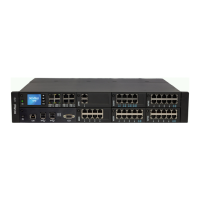
Mitel 470 as of R4.1
syd-0585/1.2 – R4.1 – 08.2016
7. Connect the earthing (see "Connecting the earthing wire", page 100).
8. Always observe the location requirements set out in Tab. 39
.
4. 2. 6. 2 Fitting an additional fan
An additional fan can be fitted in front of the standard fan already integrated. Both fans
always rotate at the same time and at the same speed, depending on the temperature
inside the communications server. The redundant fan unit increases the system’s oper-
ating reliability. If one fan fails, the second fan dissipates the heat. A fan failure gener-
ates an event message, allowing the defective fan (or both fans) to be replaced.
Note
Fans have a limited service life. So if a fan fails become of age ( approx. 5 years) it is advisable
to replace both fans as a precautionary measure.
Materials required:
• Mitel 470 additional fan premounted on fastening frame
• Set of screws for additional fan
• Screwdriver
To install the additional fan proceed as follows:
1. Shut down the communication server via the control panel (see "Call-Manager dis-
play and control panel", page 216) and disconnect it from the power supply.
Warning
Be sure to observe the "Safety regulations", page 94.
2. Remove the upper rear housing cover.
3. Remove the 4 rubber covers from the holes in the back panel of the communica-
tions server provided for mounting the additional fan.
4. Use the 4 enclosed screws to fit the fastening frame complete with additional fan to
the back panel of the communications server (see Fig. 19
).
5. Plug the fan connector into the connector marked "FAN 2" on the internal power
supply unit.
6. Fit the upper rear housing cover. In so doing follow the instructions on how to en-
sure that the backplane BP2U sits correctly, on page 98
and the corresponding dia-
gram (Fig. 20
).
7. Reconnect the communication server to the power supply.