4-225 Detailed explanation of command words
4MELFA-BASIC IV
[Explanation]
(1) Linear interpolation motion is a type of movement where the robot moves from its current position to the
movement target position so that the locus of the control points is in a straight line.
(2) The posture is interpolation from the start point to the end point.
(3) In the case of the tool coordinate system specified by using <proximity distance> or <separation dis-
tance>, the + and - directions of the Z axis vary depending on the robot model. Refer to Page 364, "5.6
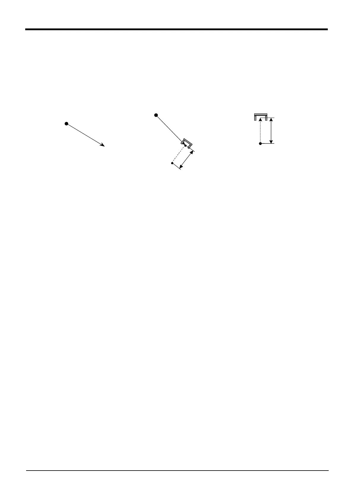
Standard Tool Coordinates" for detail. The "Fig.4-15:Example of movement at linear interpolation" is the
example of RV-6SD movement.
Fig.4-15:Example of movement at linear interpolation
(4) If paused during execution of a Mvs instruction and restarted after jog feed, the robot returns to the inter-
rupted position and restarts the Mvs instruction. This can be changed by the "RETPATH" parameter,
and also the interpolation method (JOINT interpolation / XYZ interpolation) which returns to the inter-
rupted position can be changed by same parameter. Some robots for liquid crystal transportation have
different default values of this parameter. Refer to Page 369, "5.10 Automatic return setting after jog
feed at pause".
(5) This instruction cannot be used in a constantly executed program.
(6) If the start point and end point structure flags differ when equivalent rotation (constant 2 = 0) is specified,
an error will occur at the execution.
(7) If 3-axis XYZ is designated for the numeric constant 2, the numeric constant 1 will be invalidated, and the
robot will move with the taught posture.
(8) Constant 2 designates the posture interpolation type. 3-axis XYZ is used when carrying out interpolation
on the (X, Y, Z, J4, J5, J6) coordinate system, and the robot is to move near a particular point.
MVS P1
P1
P_CURR
P_CURR
P1
MVS P1,-100
100mm
P_CURR
MVS ,-100
100mm
 Loading...