5-367 About user-defined area
5Functions set with parameters
5.8 About user-defined area
When operation is performed together with
peripheral devices, work area may have to
be shared. Under such circumstances, one
device must let the other know when it is
within the shared area. For this purpose, a
robot can be configured to output a signal
while it is in a certain area by setting
parameters.
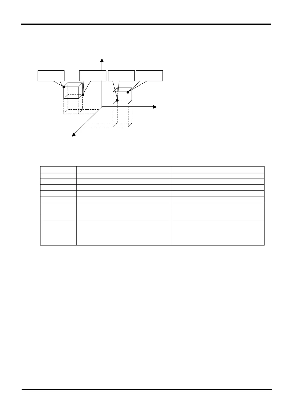
For instance, in the diagram to the left, the
following parameter setting will output the
signal 10 when operating in area (1) and
output the signal 11 when operating in area
(2).
Similar confirmation is possible using the
M_Uar variable if checking within the pro-
gram. Refer to Page 296, "M_Uar", Page
297, "M_Uar32".
*1 Enter the coordinates (x, y, and z) for x11 to z22.
*2 In the setting sample above, since the posture data (A, B, and C) are ignored, a signal will be output
regardless of the posture. To set the posture data (A, B, and C), set the values in the AREA*P1 to
AREA*P2 direction. (Example: In the case of -10 -> +30, evaluation as in-area occurs in the range from
-10 to + 30, but in the case of +30 -> -10 evaluation as in-area occurs in the range from +30 to -10.)
*3 For a non-existent axis of the posture data (for instance the A- and B-axes of horizontal multi-joint type
robots), make sure that AREA*P1 is set to -360 and AREA*P2 is set to +360.
*4 AREA*ME specifies to which mechanism will the area checking configuration apply. Under the standard
configuration (one unit is connected), this is set to 1.
*5 AREA*AT specifies the type of area checking. The meaning of the value is shown below.
0 = Does not check, 1 = Outputs a signal, 2 = Generates an error.
If 2, posture data, L1 and L2 are ignored.
*6 If additional axes are used, set an area for axes L1 and L2 respectively.
Parameter name Meaning of the value Value
AREA1P1 Position data for the first point: X,Y,Z,A,B,C,L1,L2 x11, y11, z11, -360, -360, -360,0,0
AREA1P2 Position data for the second point: X,Y,Z,A,B,C,L1,L2 x12, y12, z12, 360, 360, 360,0,0
AREA1ME Target mechanism number: Usually 1 1
AREA1AT Invalid/Output signal/Error: 0/1/2 1
AREA2P1 Position data for the first point: X,Y,Z,A,B,C,L1,L2 x21, y21, z21, -360, -360, -360,0,0
AREA2P2 Position data for the second point: X,Y,Z,A,B,C,L1,L2 x22, y22, z22, 360, 360, 360,0,0
AREA2ME Target mechanism number: Usually 1 1
AREA2AT Invalid/Output signal/Error: 0/1/2 1
USRAREA Output signal: starting number, end number 10, 11
(Information regarding whether or not the robot is in
AREA1 is output to the signal 10, and whether or not
the robot is in AREA2 is output to the signal 11.)
Set 10,10 in the case of one area.
X
Y
Z
AREA1P1
(x11,y11,z11)
AREA1P2
(x12,y12,z12)
AREA2P1
(x21,y21,z21)
AREA2P2
(x22,y22,z22)
(1)
(2)
 Loading...