5 - 9
5.2 Master Function
5.2.1 Automatic communication function
5
FUNCTIONS
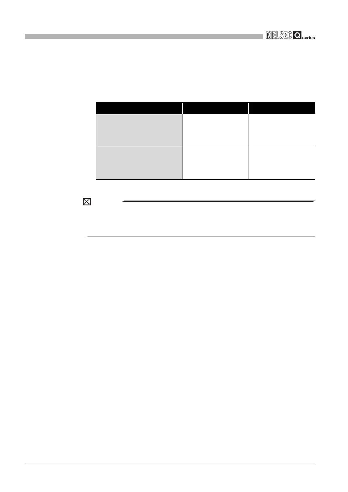
(4) Storage location for the data read/written by the automatic
communication
Data to be read or written by the automatic communication function are stored in the
following buffer memory.
POINT
1. Read/write data in the above areas are stored in RTU mode (binary) even if
the frame mode is ASCII mode.
2. Read/write data consistency is secured in units of one word (16 bits).
Table5.2 Data storage location (buffer memory)
Name Description Buffer memory address
Automatic communication function
buffer input area
Area used for storing data
read from the slave
CH1: 1000
H
to 1FFF
H
(4096 to 8191)
CH2: 2000
H
to 2FFF
H
(8192 to 12287)
Automatic communication function
buffer output area
Area used for storing data
written to the slave
CH1: 3000
H
to 3FFF
H
(12288 to 16383)
CH2: 4000
H
to 4FFF
H
(16384 to 20479)
 Loading...


