5
FUNCTIONS
5.2 Master Function
5.2.1 Automatic communication function
5 - 10
1
OVERVIEW
2
SYSTEM
CONFIGURATION
3
SPECIFICATIONS
4
MODBUS(R) STANDARD
FUNCTIONS
5
FUNCTION
6
PRE-OPERATIONAL
PROCEDURES AND
SETTINGS
7
PARAMETER SETTING
8
UTILITY PACKAGE
(GX Configurator-MB)
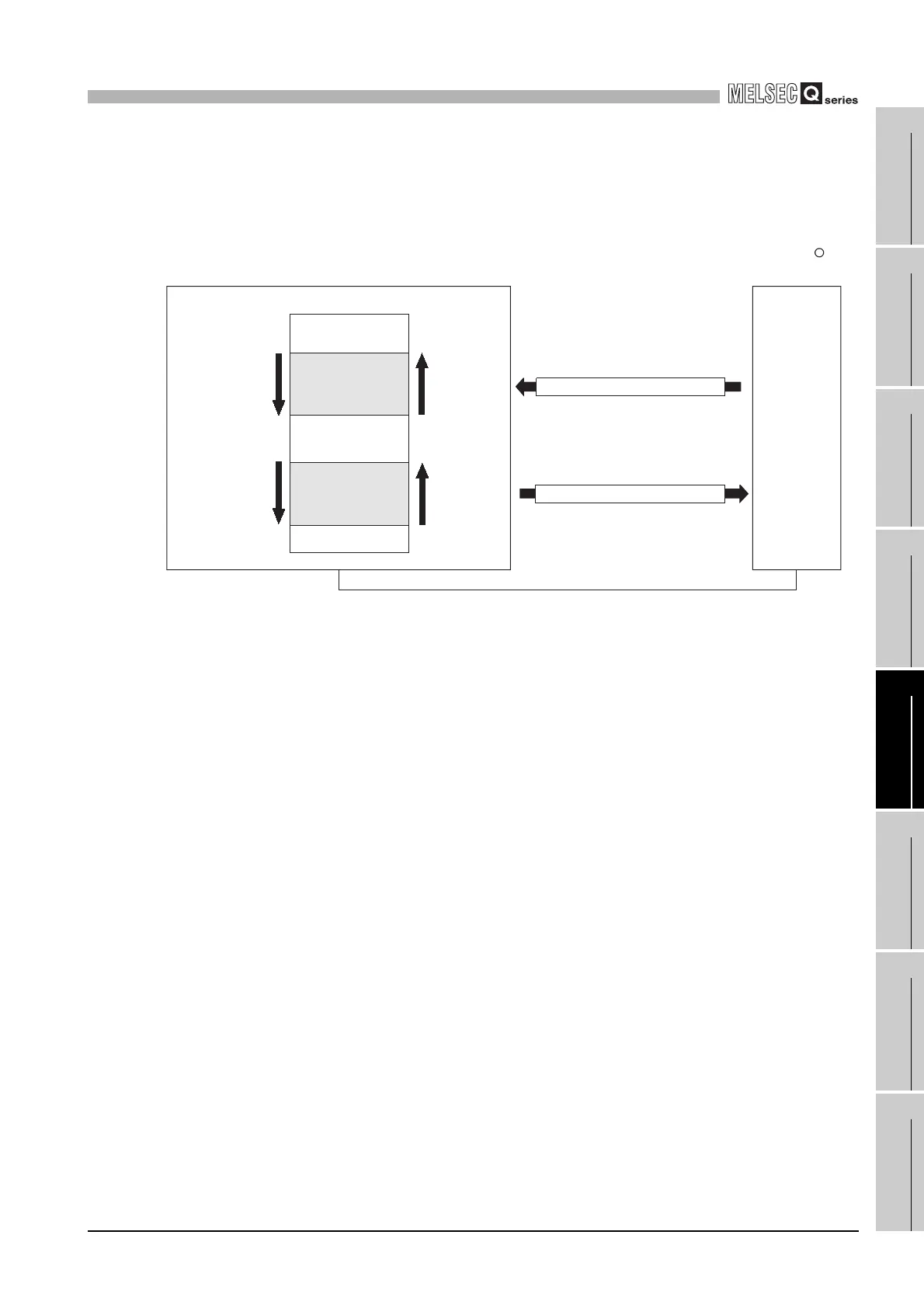
(a) Transfer direction of the automatic communication function buffer input/output
area data
The data to be stored into the buffer memory by the automatic communication
function are transferred in the following directions.
1) Transfer direction of the automatic communication function buffer input area
data
When receiving a response message from a slave, the QJ71MB91 writes data
to the automatic communication function buffer input area in descending order
of the addresses in 1 word (16 bits) unit.
2) Transfer direction of the automatic communication function buffer output area
data
When sending a request message to a slave, the QJ71MB91 creates it by
reading data from the automatic communication function buffer output area in
descending order of the addresses in units of one word (16 bits).
Figure 5.9 Transfer direction of the automatic communication function buffer input/output area data
Programmable
controller CPU
side write
direction
Programmable
controller CPU
side read
direction
QJ71MB91 (Master function)
Buffer memory
Automatic communication
function buffer input area
CH1: 1000
H to 1FFFH
CH2: 2000
H to 2FFFH
Automatic communication
function buffer output area
CH1: 3000
H to 3FFFH
CH2: 4000
H to 4FFFH
QJ71MB91
side receive
data write
direction
QJ71MB91
side send
data read
direction
Response message (data read)
Request message (data write)
RS-232, RS-422 or 485
R
MODBUS
slave device
 Loading...


