6 - 21
6.6 Intelligent Function Module Switch Setting
6
PRE-OPERATIONAL PROCEDURES AND SETTINGS
(a) Mode setting (Switch 1: CH1 side, Switch 3: CH2 side)
Set the operation mode of the QJ71MB91.
* 1 Setting a value other than indicated in the table results in a switch error.
* 2 For the link operation (slave function), set "0002
H" to both Switch 1 and 3.
Setting it to only one switch results in a switch error.
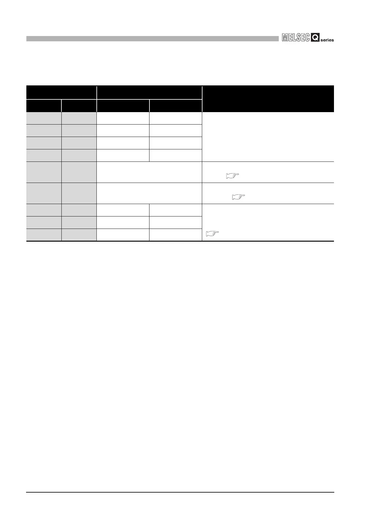
Table6.7 Mode setting
Set value
*1
Operation mode
Description
Switch 1 Switch 3 CH1 CH2
0000H 0000H Master function Master function
Master function : Performs communication as master
station.
Slave function : Performs communication as slave
station.
0000H 0001H Master function Slave function
0001H 0000H Slave function Master function
0001H 0001H Slave function Slave function
0002H 0002H
Link operation (Slave function)
*2
Relays data between CH1 and CH2 with the link operation
function. ( Section 5.3.3)
000DH 000DH Hardware test
Performs test to check the RAM and ROM of
QJ71MB91.( Section 6.4.1)
000EH 000DH Self-loopback test -
Performs tests to check the send/receive function of the
QJ71MB91 and communications with the programmable
controller CPU.
( Section 6.4.2)
000DH 000EH - Self-loopback test
000EH 000EH Self-loopback test Self-loopback test
 Loading...


