6
PRE-OPERATIONAL PROCEDURES AND SETTINGS
6.6 Intelligent Function Module Switch Setting
6 - 20
1
OVERVIEW
2
SYSTEM
CONFIGURATION
3
SPECIFICATIONS
4
MODBUS(R) STANDARD
FUNCTIONS
5
FUNCTION
6
PRE-OPERATIONAL
PROCEDURES AND
SETTINGS
7
PARAMETER SETTING
8
UTILITY PACKAGE
(GX Configurator-MB)
(2) Setting details
Details of switches 1 to 5 are shown below.
POINT
1. The settings made with the intelligent function module switches become
effective after power is switched OFF and then ON or after the programmable
controller CPU is reset.
Setting change during operation is not available.
2. When no intelligent function module switch setting has been made, the initial
values of each switch are used for operation.
3. If using the link operation function, set two channels to the same settings.
(Except for MODBUS device assignment parameter starting methods in the
transmission speed setting/transmission setting (switch 2, 4).)
Remark
For the operation method of GX Developer, refer to the following manual.
GX Developer Operating Manual
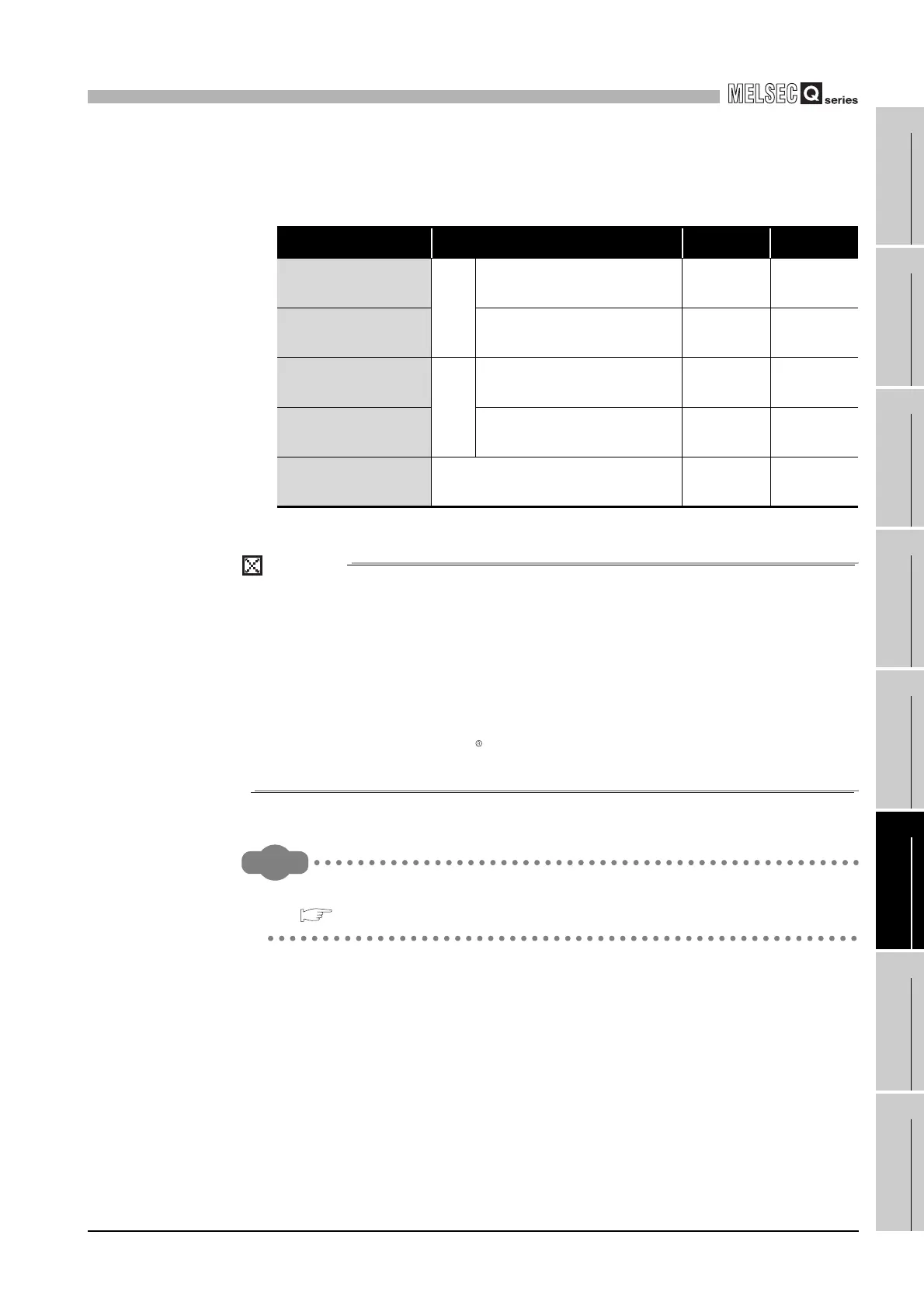
Table6.6 Intelligent function module switch
Switch No. Description Default Reference
Switch 1
CH1
Mode setting 0000
H
This section
(2) (a)
Switch 2
Communication speed/transmission
setting
0700
H
This section
(2) (b)
Switch 3
CH2
Mode setting 0000
H
This section
(2) (a)
Switch 4
Communication speed/transmission
setting
0700
H
This section
(2) (b)
Switch 5 CH1,2 station No. setting 0000
H
This section
(2) (c)
 Loading...


