7
PARAMETER SETTING
7.3 MODBUS(R) Device Assignment Parameter
7.3.1 MODBUS(R) device assignment to the programmable controller CPU device memory
7 - 14
1
OVERVIEW
2
SYSTEM
CONFIGURATION
3
SPECIFICATIONS
4
MODBUS(R) STANDARD
FUNCTIONS
5
FUNCTION
6
PRE-OPERATIONAL
PROCEDURES AND
SETTINGS
7
PARAMETER SETTING
8
UTILITY PACKAGE
(GX Configurator-MB)
(2) Setting details
(a) Before performing setting
With the intelligent function module switch, turn ON the MODBUS device
assignment parameter starting method (switch 2, bit 0).( Section 6.6)
If this switch is set to OFF, the operation will proceed based on the default
assignment parameters.
( This section (3))
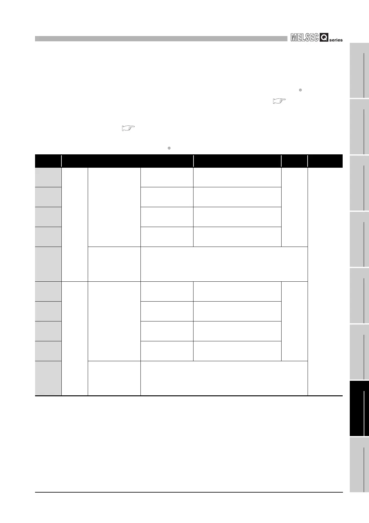
(b) Setting parameter list
(Continued on next page)
Table7.6 MODBUS device assignment parameter list
Address Parameter name Setting range Default Reference
0900
H
(2304)
Coil
Coil assignment 1
Device code
0000
H: Device code not assigned
Other than 0000
H: Device code
0000
H
This section
(2) (b) 1) to 4)
0901
H
(2305)
Head device number 0000
H to FFFFH
0902
H
(2306)
Head coil number 0000
H to FFFFH
0903
H
(2307)
Assignment points 0000
H to FFFFH
0904
H
to
093F
H
(2308 to
2367)
Coil assignment 2 to
16
(Same as in Coil assignment 1)
0940
H
(2368)
Input
Input assignment 1
Device code
0000
H: Device code not assigned
Other than 0000
H: Device code
0000
H
0941
H
(2369)
Head device number 0000
H to FFFFH
0942
H
(2370)
Head input number 0000
H to FFFFH
0943
H
(2371)
Assignment points 0000
H to FFFFH
0944
H
to
097F
H
(2372 to
2431)
Input assignment 2 to
16
(Same as Input assignment 1)
 Loading...


