11 - 3
11.1 Troubleshooting
11
TROUBLESHOOTING
(2) Troubleshooting of errors indicated by X signals
(Continued on next page)
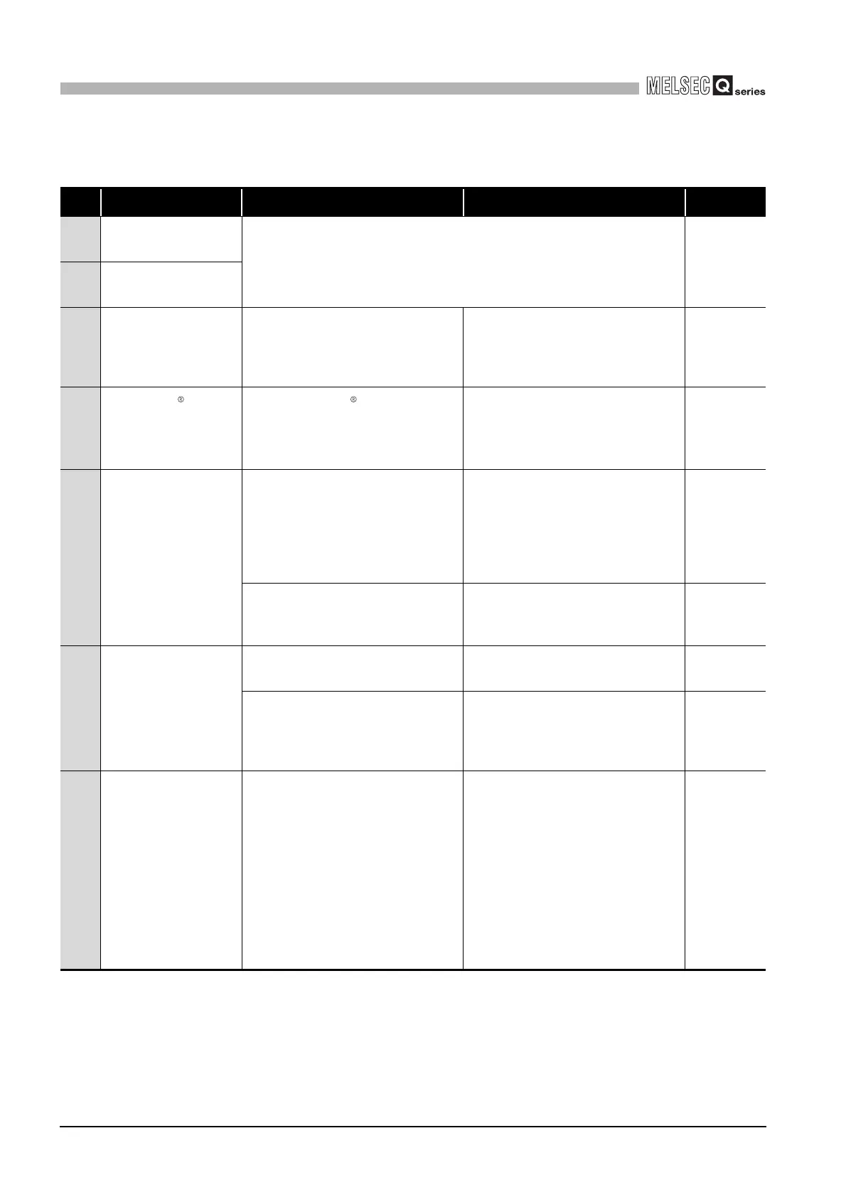
Table11.2 Troubleshooting of errors indicated by X signals
No. Symptom Check point Corrective action Reference
1
The Module READY (X0)
turned off.
Refer to "The RUN LED turned off."
This section
(1)-1
2
The Watch dog timer error
(X1F) turned on.
3
The Automatic
communication parameter
setting, error completed
(X5/XD) turned on.
Check the Automatic communication
parameter error code storage area
(address: 0C16
H
/0C18
H
) in the buffer
memory and identify the error code.
Take corrective actions for the error code
and retry.
Section 11.4
4
The MODBUS device
assignment parameter
setting, error completed
(X9) turned on.
Check the MODBUS device
assignment parameter error code storage
area (address: 0C13
H
) in the buffer
memory and identify the error code.
Take corrective actions for the error code
and retry.
Section 11.4
5
The Automatic
communication operation
status (X6/XE) does not
turn on.
Check if the automatic communication
function is activated.
Set the automatic communication
parameters by GX Configurator-MB and
activate them.
Or, set the automatic communication
parameters by a sequence program and
activate them.
Section 7.2
Section 9.1.1
Check if the Automatic communication
parameter setting, error completed (X5/
XD) is on.
Refer to "The Automatic communication
parameter setting, error completed (X5/
XD) turned on."
This section
(2)-3
6
The Automatic
communication operation
status (X6/XE) turned off.
Check if the Automatic communication
stop request (Y6/YE) has been issued.
Restart the automatic communication
function.
Section 5.2.1
Was the UINI instruction executed?
After execution of the UINI instruction, set
the automatic communication parameters
atain, and start the automatic
communication function.
Section 7.2
7
The Automatic
communication error
status (X7/XF) turned on.
Check if the communication with the target
device is possible.
Check the Automatic communication
operation status storage area (0C20
H to
0C21
H/0C22H to 0C23H) in the buffer
memory and identify the parameter
number of the error cause.
Take corrective actions according to the
error code currently stored in the
Automatic communication error code
storage area (0C28
H to 0C47H/0C48H to
0C67
H) or the exception code sent from
the target slave.
Section 11.4
 Loading...


