4 - 13
4.2 Frame Specifications
4.2.1 Frame mode
4
MODBUS(R) STANDARD FUNCTIONS
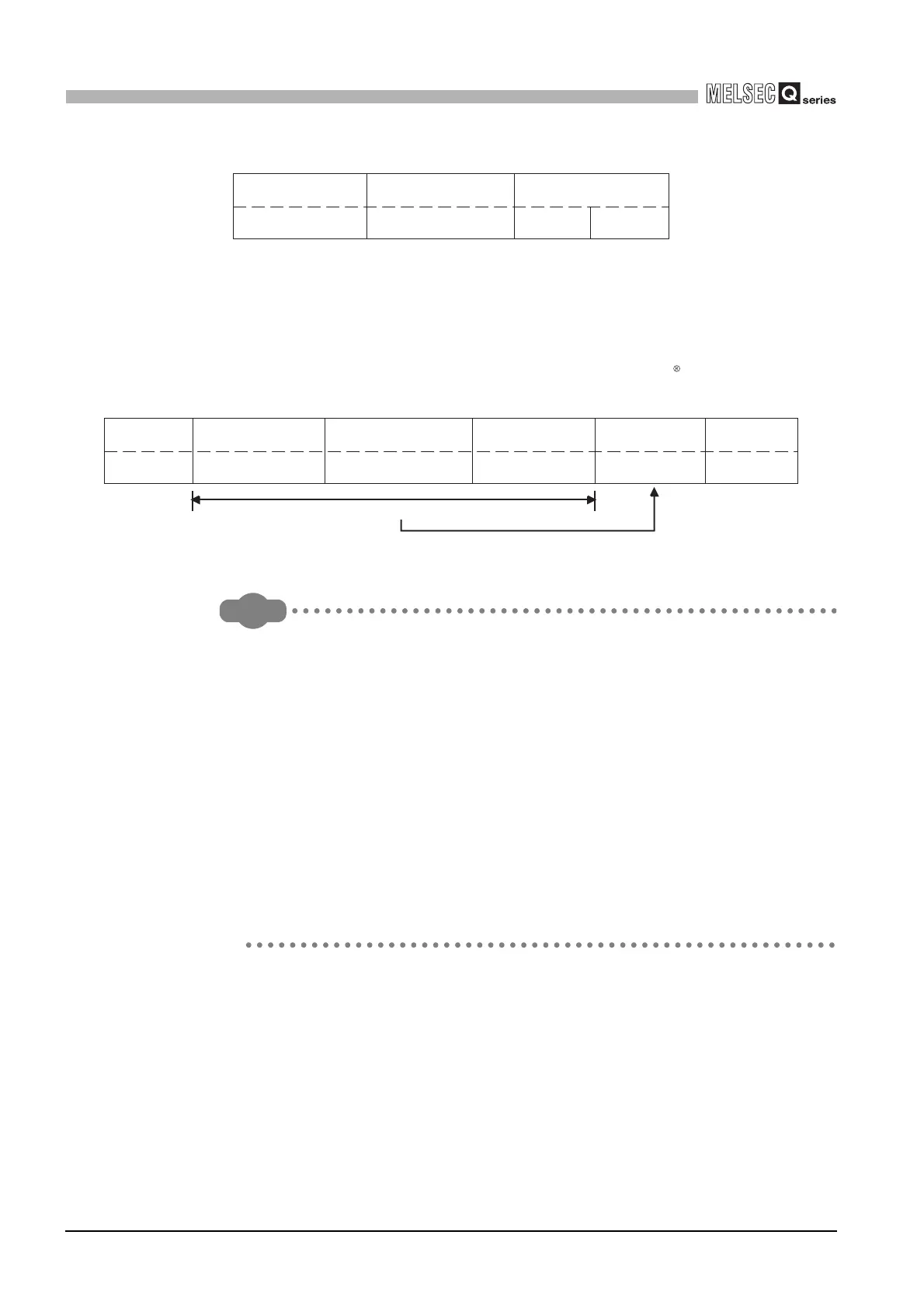
(b) ASCII mode
In this mode, frames are received or sent in units of 2 characters (2 bytes) in
ASCII codes.
The frame specifications are compliant with the MODBUS protocol
specifications.
Remark
The error check in the ASCII mode is conducted by LRC (Longitudinal
Redundancy Check).
The QJ71MB91 calculates the LRC by the following steps.
Please follow the same steps to calculate the LRC when conducting an error
check on the target device.
1) To calculate the LRC, convert the ASCII codes within the error check range
into the RTU format (binary).
2) Add the figures in units of contiguous 8 bits in the frame. (Excluding carries
during addition.)
3) Change the result of the above 2) to a 2's complement. (Reverse the bits and
add 01
H.)
4) Convert the result of 3) to an ASCII code.
Figure 4.3 Frame for CRC calculation
Figure 4.4 Frame in ASCII mode
Address field
(02
H) (07H)
Function code CRC (Error check)
(41H) (12H)
Start END
Error check calculation range
Address field
:
(3A
H)
2 characters
Function code
2 characters
Data
Error check
n x 2 characters
(n = 0 to 252)
2 characters
CR + LF
(0D
H
) (0A
H
)
 Loading...


