4
MODBUS(R) STANDARD FUNCTIONS
4.2 Frame Specifications
4.2.1 Frame mode
4 - 14
1
OVERVIEW
2
SYSTEM
CONFIGURATION
3
SPECIFICATIONS
4
MODBUS(R) STANDARD
FUNCTIONS
5
FUNCTION
6
PRE-OPERATIONAL
PROCEDURES AND
SETTINGS
7
PARAMETER SETTING
8
UTILITY PACKAGE
(GX Configurator-MB)
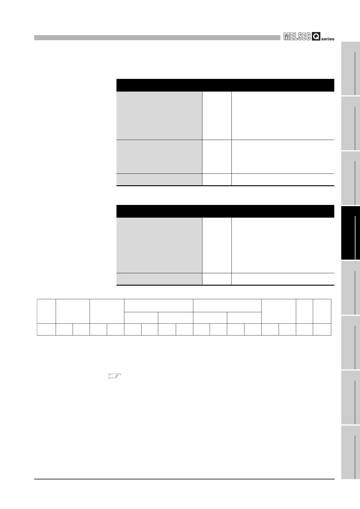
The following are calculation examples in the case where function code 01H is
sent to station No. 2.
(2) Frame mode setting
The frame mode is set in the intelligent function module switch setting.
( Section 6.6)
Table4.6 LRC calculation procedure (when sending a request message)
LRC in request message transmission
Station No. (address field)
Function code
Head coil number (H)
Head coil number(L)
Read points (H)
Read points (L)
02
01
00
00
00
08
0000
0000
0000
0000
0000
+0000
0010
0001
0000
0000
0000
1000
Addition result
Bit reversal 1
+1
2's complement
0B
F4
F5
0000
1111
1111
1011
0100
1
0101
LRC (Error check) F5 F 5
Table4.7 LRC calculation procedure (when receiving a response message)
LRC in reception of a response message
Station No. (address field)
Function code
Head coil number(H)
Head coil number(L)
Read points (H)
Read points (L)
LRC (Error check)
02
01
00
00
00
08
F5
0000
0000
0000
0000
0000
0000
+1111
0010
0001
0000
0000
0000
1000
0101
Addition result 00 0000 0000
Figure 4.5 Frame for LRC calculation
Head input number Read points
Start
:
Address field
(02
H
)
Function code
(01
H
)
CRC
(Error check)
(F5
H
)
3A
H
30
H
32
H
30
H
31
H
(00
H)
(00
H)
(00
H)
(08
H)
30
H
30
H
30
H
30
H
30
H
30
H
30
H
38
H
46
H
35
H
0D
H
"CR" "LF"
0A
H
 Loading...


