Sec 1: 8-18 Disassembly/Reassembly Procedures: Radio Disassembly
8.7.7 Removal of the VOCON Board Assembly (D)
NOTE: Reconfirm the Flex connector between the Control Top Assembly (F) and the
VOCON Board Assembly (D) is disconnected. Failure to do so may damage the
connectors or the flex.
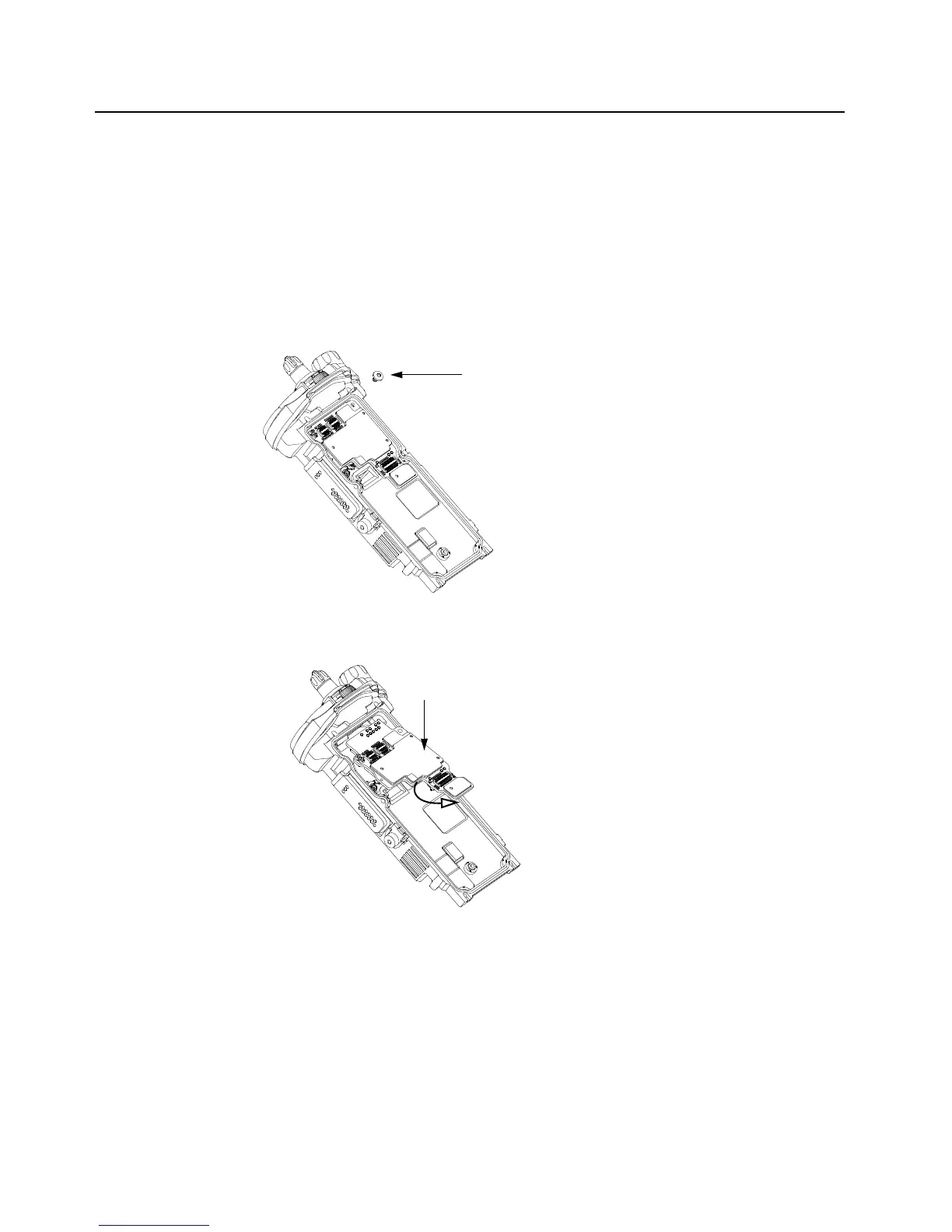
1. Ensure RF Board is removed (see Section 8.7.6 on page 1:8-17.). Remove RF and VOCON
Board screw (45) (as shown in Figure 8-24.), Gently rotate the VOCON Board Assembly just
enough to clear the Main Chassis. Slide out the VOCON Board Assembly as shown in
Figure 8-25.
Figure 8-24. Remove VOCON Board Screw
Figure 8-25. Remove VOCON Board Assembly
RF and VOCON Board Screw (45)

 Loading...


