Disassembly/Reassembly Procedures: Radio Disassembly Sec 1: 8-17
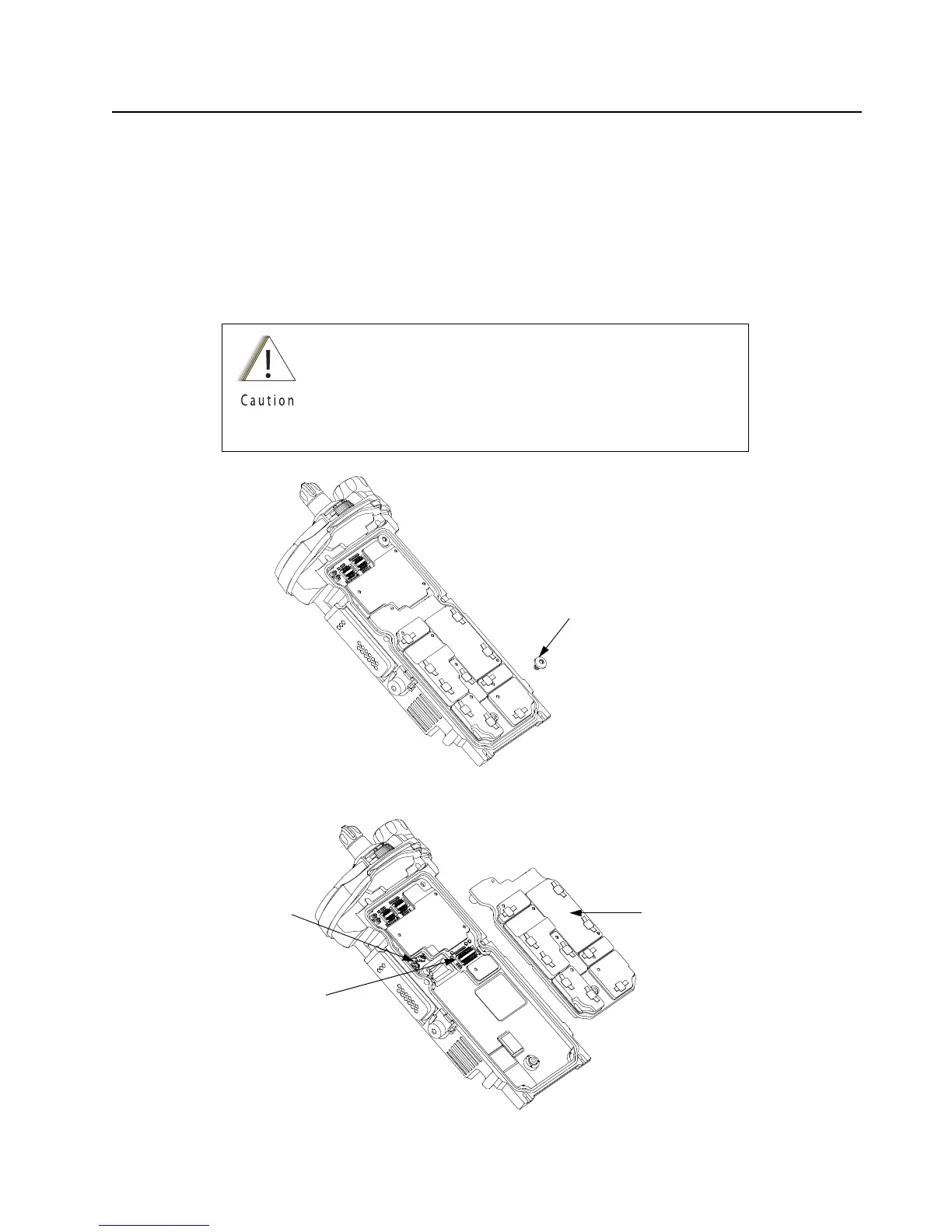
8.7.6 Removal of the RF Board Assembly (C)
NOTE: Reconfirm the coax cable connector on the bottom side of the RF Board is
disconnected before removing the RF Board.
1. Remove the RF and Vocon Board screw (45) then unplug the RF Board Assembly (C) from
the VOCON Board Assembly (D) by using the Black Stick. Slowly lift the RF Board Assembly
enough to allow access to the small coax cable. Unplug the small coax cable using a Black
Stick or a pair of small tweezers.
Figure 8-22. Remove RF Board Screw
Figure 8-23. Remove RF Board Assembly
Place the RF Board Assembly in a clean and ESD safe area
to avoid contamination to the Battery Connector Seal (13) and
electrical damage to the electronics respectively.
Replace Thermal Pads (10, 11) whenever RF Board
Assembly is removed.
RF and Vocon Board Screw (45)
Connector
RF Board Assembly (9)
Small Coax Cable

 Loading...


