6878215A01
Options and Accessories Installation Accessory Connector Assembly Details (P2) (All Models Except 100W) 4-11
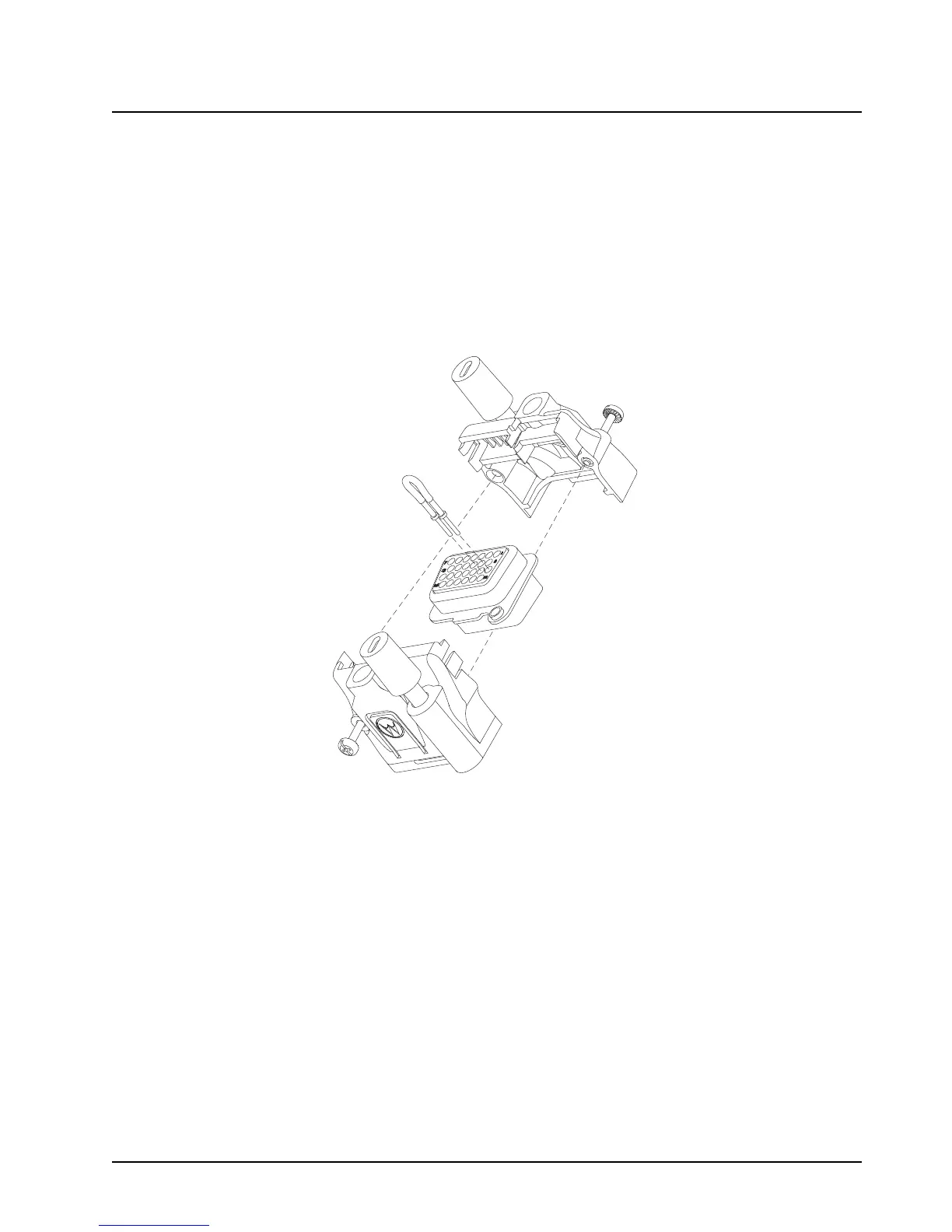
4.5.1.2 Assembly
1. Place the plug in one cover. Be sure that the flange of the plug is in the slot of the cover.
See Figure 4-11.
2. Push the jackscrew through the plug to hold it in.
3. Position each wire across the strain-relief features in the cover. Avoid damaging loads on the
plug by allowing some slack in each wire in the accessory connector assembly’s wire
chamber.
4. Place the second cover onto the plug. Be sure that the flange is protruding through both
covers.
Figure 4-11. Exploded View of Accessory Connector Assembly (HLN6863_)
5. Squeeze the covers together bending the wires in the strain-relief features. You may need a
pair of pliers to seat the assembly covers.
6. Once the covers are fully seated, fasten them with the cover screws. Tighten the screws
firmly but do not over-tighten them. Be sure none of the wires are pinched.
7. Reattach the accessory connector assembly to the back of the radio and fasten it by
finger-tightening the jackscrews to prevent any loosening.
NOTE: See APX Mobile Basic Service Manual (6875964M01) for more detailed descriptions of these
pins and other connectors located in the APX mobile radio.

 Loading...


