6878215A01
Standard Configurations Power Cables (Transceiver and Control Head) 2-37
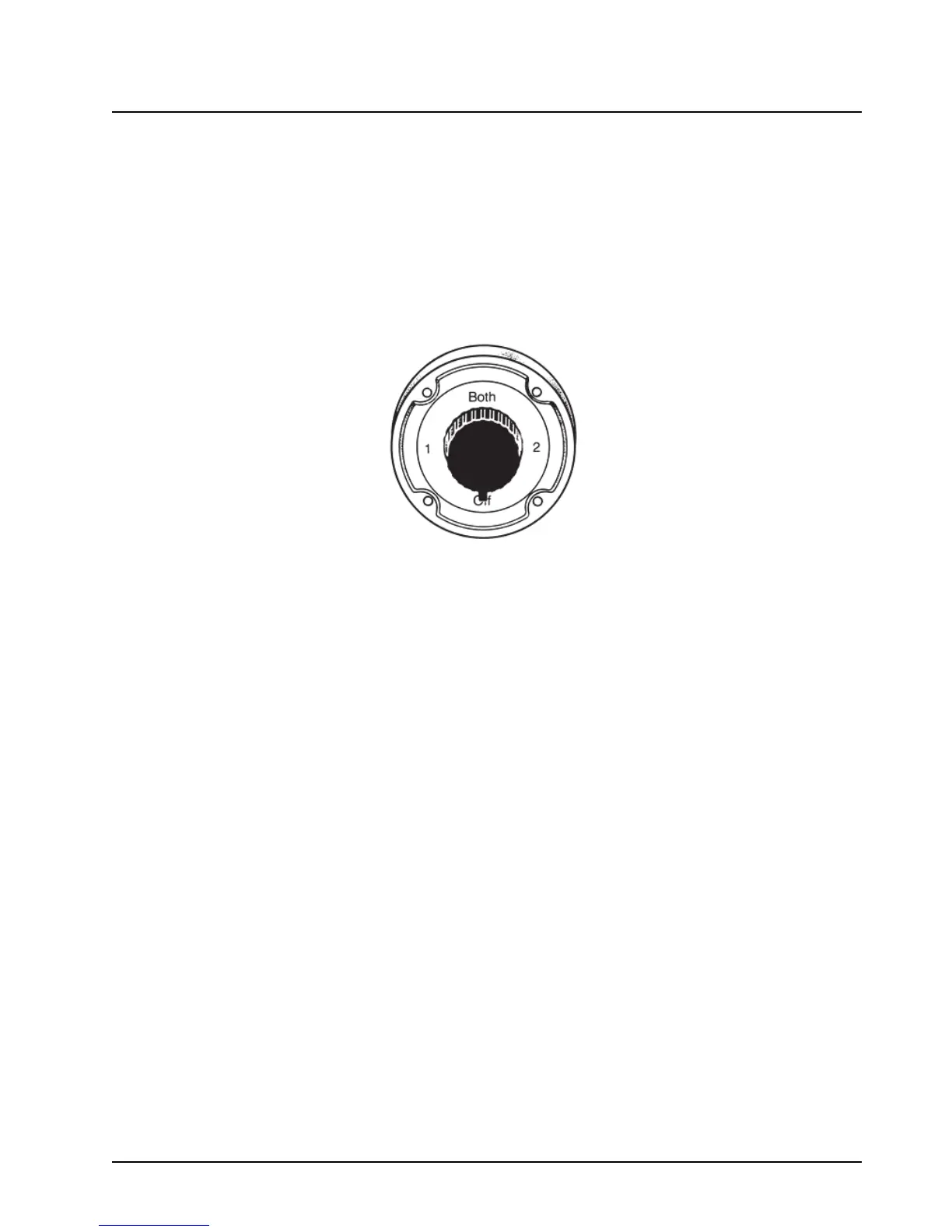
2.3.3 Battery Selector Switch
In vehicles which have installed a Battery Selector Switch, the ignition sense (yellow) wire should be
the only wire connected to the battery selector switch (see Figure 2-48). Radio transceiver and
control head power wires (red) must be connected directly to the vehicle battery. If the control head
power wire and the control head ignition sense wire are both connected to a battery selector switch,
but the radio transceiver power lead is not, improper power-cycling and off-state battery drainage
may occur. If the desired state of the radio is a total battery drain elimination, then all power and
ignition sense wires must be routed through the battery selector switch, so that the control head and
radio transceiver both see the loss of battery power at the same time.
Figure 2-48. Battery Selector Switch

 Loading...


