6878215A01
Standard Configurations Speaker 2-45
4. Put the control head face down on a clean, flat surface to avoid damaging it. Do not touch the
o-ring on the back housing.
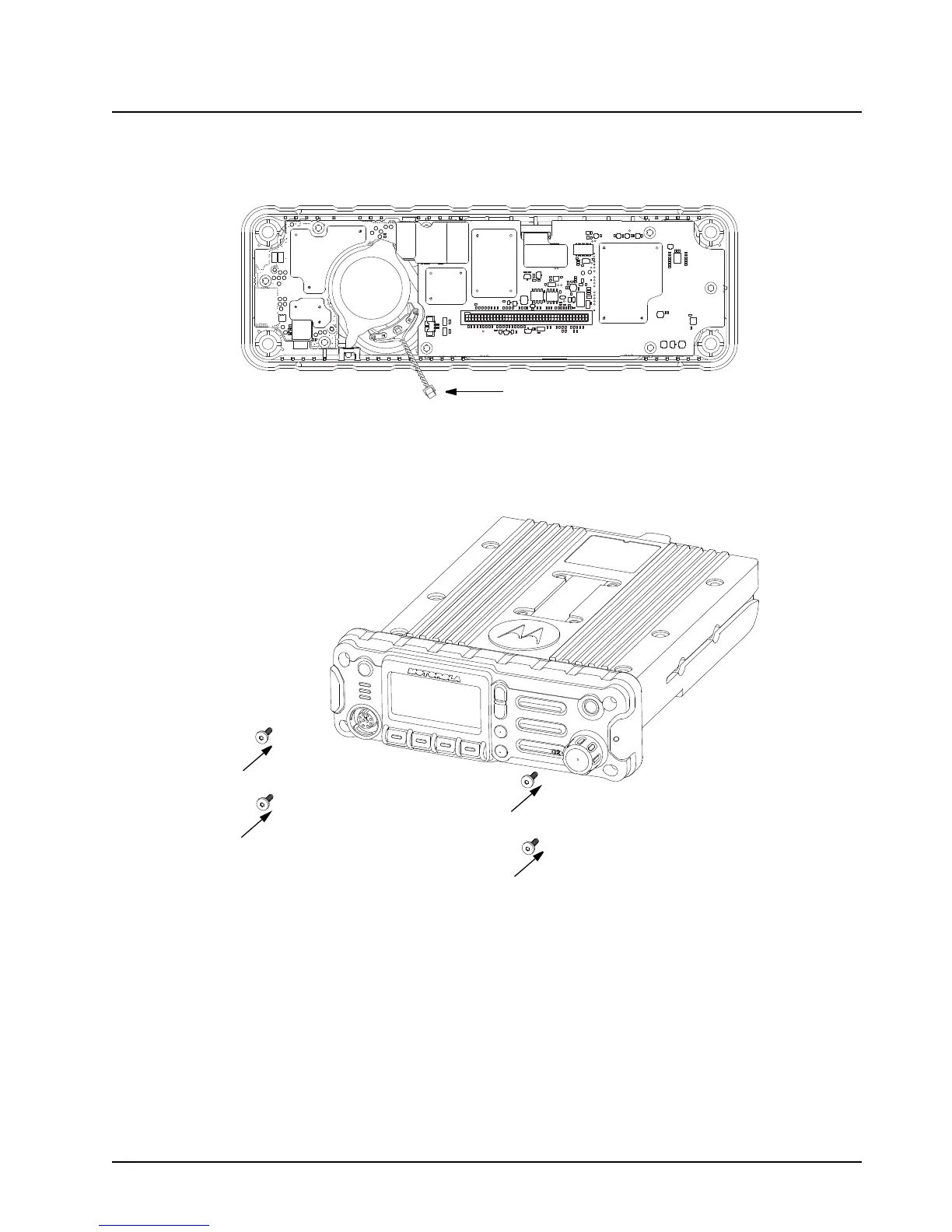
5. Carefully disconnect the speaker connector from the circuit board as shown in Figure 2-59.
Figure 2-59. Disconnecting the Speaker Connector
6. Reattach the front housing assembly to the back housing assembly as shown in Figure 2-60.
Make sure that the flex is returned to its original position and that the o-ring on the back
housing assembly is not pinched.
Figure 2-60. Reattaching the Control Head
7. Secure the front housing assembly back to the back housing assembly with four new screws
using the Torx T-20 bit as shown in Figure 2-60. Apply 9 in. lbs. torque for each screw.

 Loading...


