6878215A01
Standard Configurations Radio Mounting 2-27
Figure 2-31. O9 Control Head Rear View
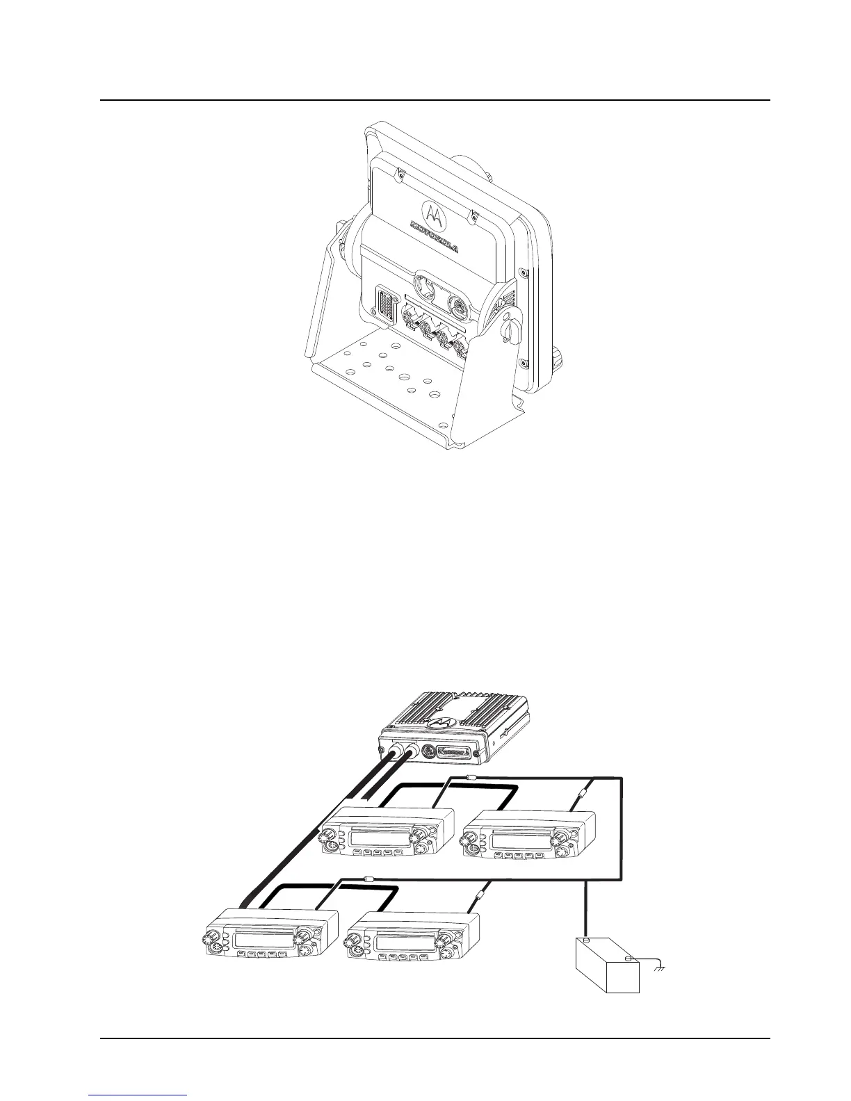
2.2.2.3 Multiple Control Head Installation
Control heads in a multiple control head configuration should be installed per the steps detailed in
Section 2.2.2.2: “Remote Mount Control Head Installation” on page 2-24. Two heads can be
connected to each of the two CAN connectors on the transceiver, with the remaining heads
connected to one or both of the first two. Control heads can also be connected a “daisy chain”
configuration from a single transceiver CAN connector. See Figure 2-32 for examples.
NOTE: The transceiver must be configured for Multiple Control Head via CPS programming.
Navigate to the “Control Head” tab in the Radio Wide section of CPS, and select “Help” for
further information and tutorials.
Control Head 1
Control Head 2
J300R
J300R
J200
J200
J300L
(-)
RED LEAD
(+)
BATTERY
FUSE
FUSE
FUSE
FUSE
Control Head 3
Control Head 4
J300R
J200
J200
J300L
J300R

 Loading...


