6878215A01
5-18 Motorcycle Radio Installation Installing the Antenna
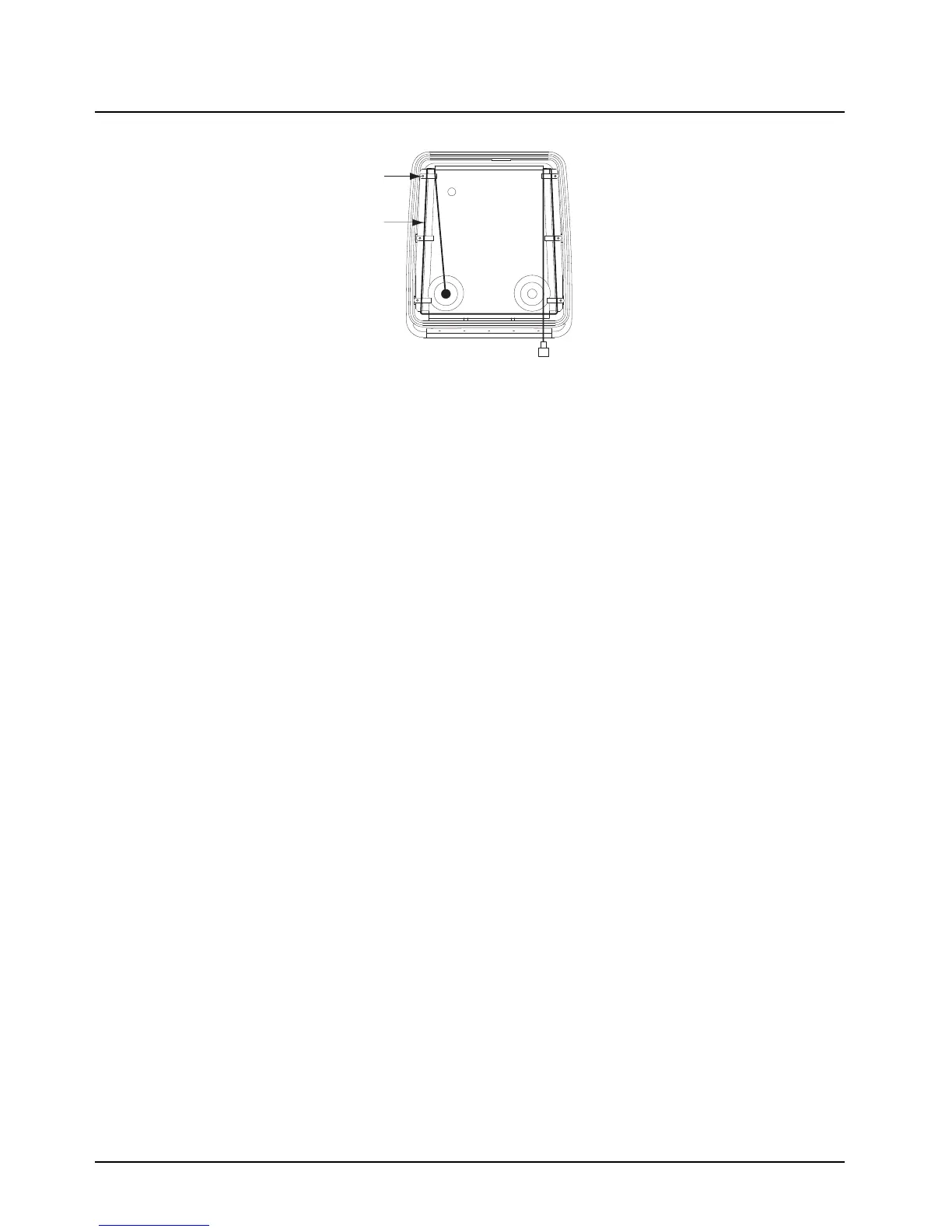
Figure 5-13. Routing the Coaxial Cable for Band 2
14. After routing cable, allow enough of the cable to reach the radio’s antenna connector and cut
off any excess length of the cable.
15. Install the connector per Antenna Installation Manual.
5.8 Installing the Antenna
IMPORTANT: Antenna Placement and Cable Routing as described inside the
Antenna Installation Manual is not applicable for the APX radio
series. Refer to information listed below.
• Connect the appropriate antenna connectors to the antenna receptacles on the radio. Tighten
the coupling until fully engaged.
5.9 Cable Routing
Five cables must be installed to interconnect the components of the radio system as shown in
Figure 5-14. The antenna cable is routed away from the other cables inside the enclosure’s hinged
cover (see Section 5.7 on page 5-15). The four remaining cables, routed along the motorcycle frame,
are described in the following paragraphs.
NOTE: Antenna Hole Placement and Cable Routing information in the Antenna Installation Manual
is not applicable to the APX series.
Removal of the fuel tank and seat from the motorcycle will facilitate routing the cables along
the frame. Motorcycles with consoles attached to fuel tanks require routing cables between
console and fuel tank. In this case the tank is not removed.
Cable
Clamp
Coaxial
Cable
Attach to Antenna
Connector on
Radio Band 2

 Loading...


