6878215A01
Options and Accessories Installation Vehicle Interface Port Overview 4-7
4.3.1 VIP Output Connections
The VIP output pins are on the back of the control head (J100 and J400), or the rear accessory port
(J2), as shown in Figure 2-10, Figure 4-12 and Figure 4-13, respectively. Use these connections to
wire control relays. One end of the relay should connect to switched B+ voltage, while the other side
connects to a software controlled ON/OFF switch inside the control head. The relay can be normally
on or normally off depending on the configuration of the VIP outputs. There are three VIP output
connections, as follows:
The function of these VIP outputs can be field programmed in the control head. Typical applications
for VIP outputs are external horn/lights alarm and horn ring transfer relay control. For further
information on VIP outputs, see the control head programming manual.
VIP OUT 1 and VIP OUT 2 can be accessed from either J100 or J400 connectors. This is to allow a
previously wired VIP OUT at J2 to move easily to J100. However, when any cable is inserted into
J400, J100 VIP OUTs are disabled.
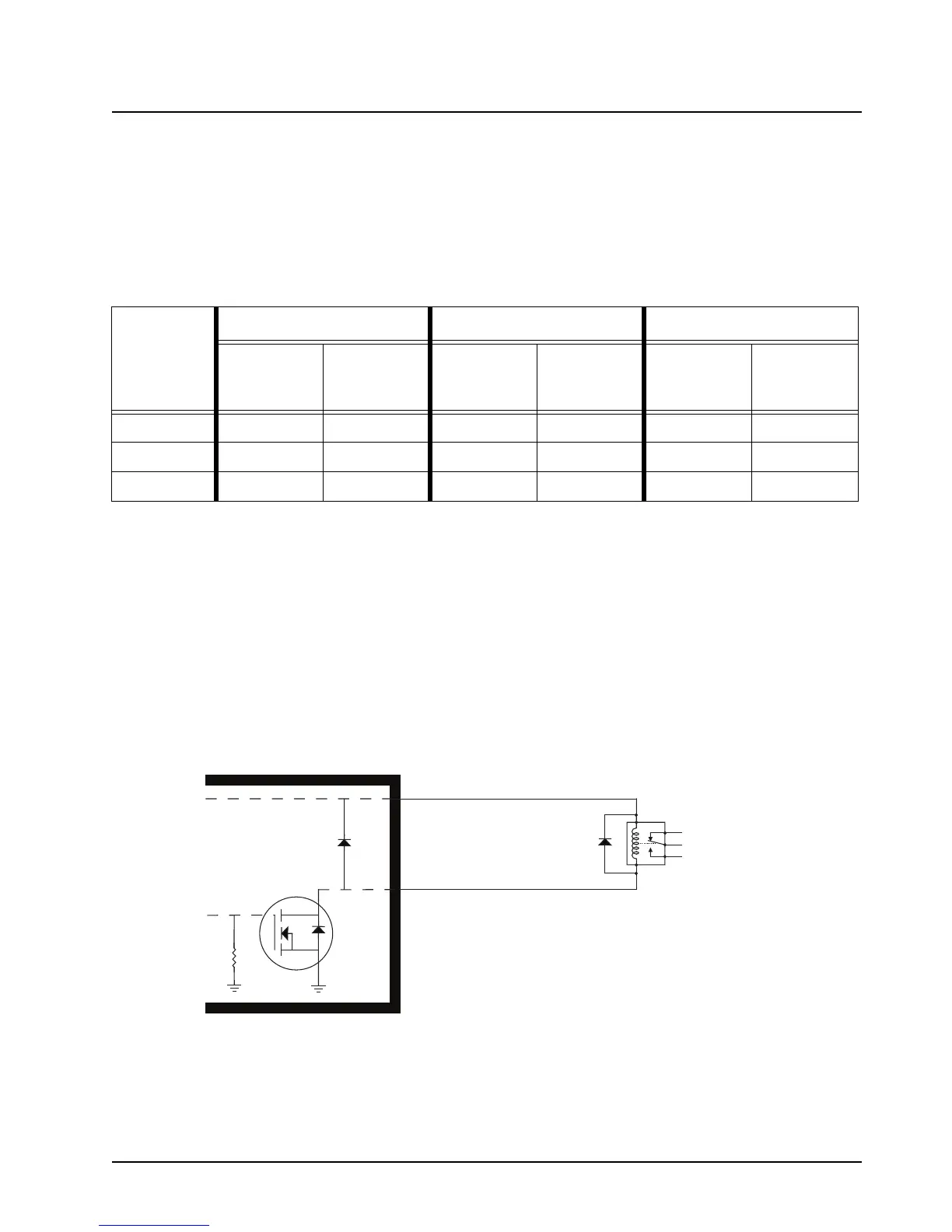
When installing relays to the VIP OUT lines, a diode is necessary to prevent damage to the transistor
or MOSFET, due to “back EMF” when the field collapses on the relay coil. Some vendor relays
already come with this diode built-in, and other relays require the customer to install it. Figure 4-8
shows the proper placement of the diode across the relay coil. The transistor or MOSFET is located
inside the radio or the D.E.K. box.
Figure 4-8. Relay Coil
NOTE: See Appendix A: Replacement Parts Ordering to order relay’s for your VIP OUT applications.
Example relay hardware: TLN4533_ (relay without internal diode), HLN6969_ (relay with
internal back EMF protection diode), and HKN4258_ (relay wiring cable).
Table 4-1. VIP Output Connections
VIP OUT #
J400 J2 J100
SW B+ Pin
Number
On/Off
Switched Pin
Number
SW B+ Pin
Number
On/Off
Switched Pin
Number
SW B+ Pin
Number
On/Off
Switched Pin
Number
1 Red 1 5 (Blue) 24 18 24 18
2 Red 1 6 (Yellow) 24 19 24 19
3Red 17 (Black)NANANANA
N.C.
N.O.
Relay
G
D
S
VIPout
SW B+
Note:
To 'activate' a VIPOUT, you have to ground the VIPOUT, such that the
current now flows thru the relay coil to GND through a MOSFET inside
the radio or control head, which causes the relay wiper to toggle. The
MOSFET of a VIPOUT should never be used to directly drive an
accessory. The MOSFET should be used to control an external relay.
Protection
Diode

 Loading...


