Chapter 1 Introduction
This manual covers the installation procedures for ASTRO APX mobile and motorcycle radios with
O2, O3, O5, O7 and O9 control heads, and accessories required to complete the radio system. The
radio system consists of a control head, radio, antenna, microphone, speaker, cabling, Universal
Relay Controller (URC), and accessories.
1.1 Mobile Radio Description
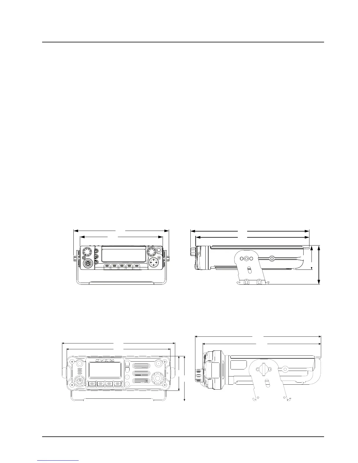
1.1.1 Dimensions
Figure 1-1, Figure 1-2, Figure 1-3 and Figure 1-4 show the basic dimensions of the dash mount
transceiver trunnion APX mobile radio. The transceiver portion of a remote mount APX mobile is
sized similarly.
When installing the radio, make sure to plan the installation carefully and leave additional room in the
rear of the radio for cabling and accessory connections; in the front of the radio for access, controls,
and cabling (if remote mount); and to the sides of the radio so that you may access and install the
trunnion screws/wing screws.
NOTE: The measurement unit used in Figure 1-1 to Figure 1-22 is millimeter.
NOTE: The rear accessory connector adds 0.75 in to the overall length. The remote mount length
is 244 mm.
Figure 1-1. Front View of APX 7500
Mid Power Dash Mount Transceiver and Trunnion
Figure 1-2. Side View of APX 7500 Mid Power
Dash Mount Transceiver and Trunnion
Figure 1-3. Front View of APX 2500/4500
Mid Power Dash Mount Transceiver and Trunnion
Figure 1-4. Side View of APX 2500/4500
Mid Power Dash Mount Transceiver and Trunnion

 Loading...


