6878215A01
Standard Configurations Radio Mounting 2-25
An adjustable trunnion, which allows a number of mounting positions, is supplied for mounting the
control unit. The installation must not interfere with the operation of the vehicle or its accessories, nor
disturb passenger seating or leg room. The control head must be within convenient reach and
viewing of the user.
If the trunnion is mounted on a plastic mounting surface, all four mounting screws should penetrate
the mounting surface’s supporting metal frame. If that is not possible, use a metal backing plate (not
supplied) to strengthen the installation. Install the control follows:
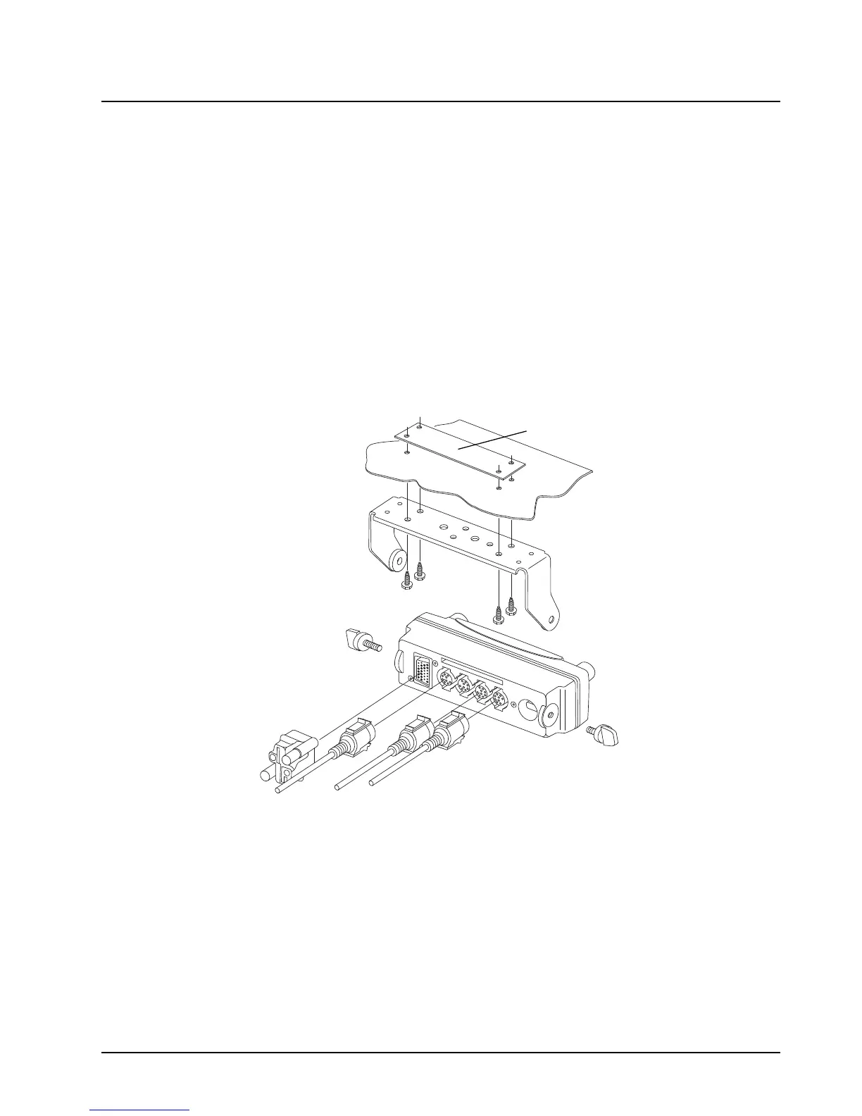
1. Use the control unit trunnion as a template to mark the mounting holes; drill 5/32" holes.
If mounting on a plastic surface, use a metal backing plate.
2. Attach the trunnion bracket using all four 10-16" x 5/8" self-tapping screws provided.
3. Temporarily install the control head (adjusting for proper viewing angle) and fasten it to the
trunnion with two wing screws. Test the installation to be sure the control head feels securely
locked in place while you are pressing its buttons.
4. Finish installation by fully tightening screws.
Figure 2-28. O5 Control Head Installation Exploded View
(Also applicable for O2 and O7 Control Heads)
Metal Backing Plate
(Not Supplied)

 Loading...


