6878215A01
Standard Configurations Radio Mounting 2-31
A mounting clip, which allows the control head to be mounted, is supplied together with the control
head. The installation must not interfere with the operation of the vehicle or its accessories, nor
disturb the passenger seating. The control head must be within convenient reach and viewing of the
user.
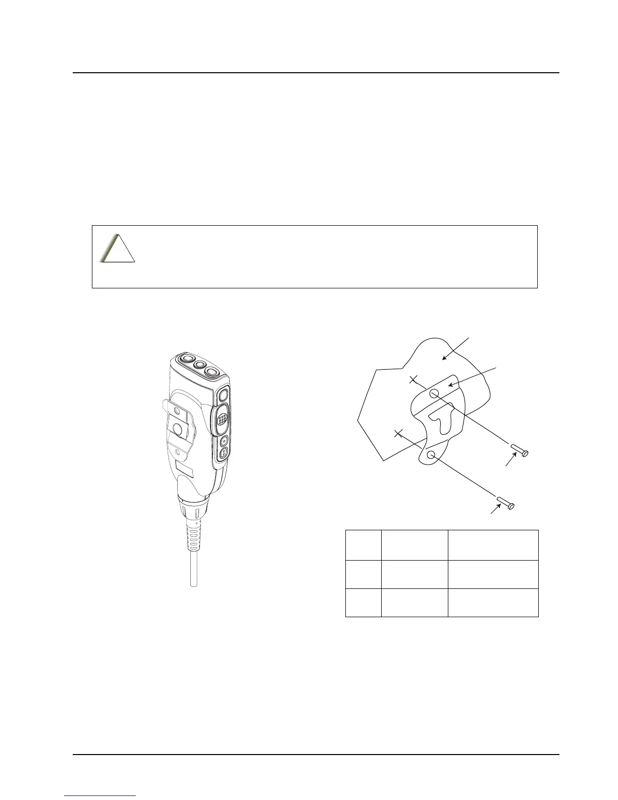
Install the mounting clip as follows:
1. Use the provided mounting clip to determine the location of the two screw holes.
2. Drill 7/16” deep holes for upper and lower screws.
3. Use the tapping screw provided to install the mounting clip.
Care must be taken to shield the control head (front and back) from direct exposure to
pressurized water. The pressurized water from a hose, in most cases, is more severe
than the stated test and conditions in typical environments.
Figure 2-37. O3 Control Head Rear View Figure 2-38. Hang-Up Clip Installation
Exploded View
2
2
1
Vehicle Mounting Surface
Item
No.
Part Number Description
1 01-80743T91 Mic Hang-Up Clip
Assembly
2 03-07644M19 Screw, Machine,
8-32 x 7/16

 Loading...


