6878215A01
Motorcycle Radio Installation Installing Antenna Base and Cables 5-15
5.6.3 Other Hang-Up Clip Mounting
To mount the microphone hang-up clip in another location, a customer-supplied bracket may be
used. Suggested locations include the handlebars, fuel-tank console, or any location which provides
easy access to the microphone without blocking controls and indicators and without interfering with
motorcycle handling. See Figure 5-5, Figure 5-6, and Figure 5-7 for alternative microphone hang-up
clip mounting methods.
1. Fabricate a bracket, then secure it to the motorcycle.
2. Use two machine screws, lock washers, and nuts to secure the hang-up clip to the
customer-supplied bracket. Ensure that the microphone clip is DC grounded to the
motorcycle chassis (a grounding lug and strap are provided in the hang-up clip kit for this
purpose) – this is essential for proper radio operation.
5.7 Installing Antenna Base and Cables
NOTE: Antenna hole placement and cable routing in 7/800, VHF and UHF antenna manuals are not
applicable for the APX Series.
The GPS antenna assembly must be done after the removal of the metal liner but before
reinstalling the APX Series liner.
1. Open the top cover of the weather-resistant enclosure.
2. Uninstall the metal liner that is shipped attached to the weather-resistant enclosure. This liner
has one depressed area at the top of the enclosure liner just toward the rear of the enclosure.
This metal liner is not used with APX Series products.
3. Place the metal liner with two round, depressed areas toward the enclosure hinge and 5/8”
hole near the front of the housing, inside the top cover, and align the six slots in the metal
liner with the screw holes in the top housing.
4. The metal liner of the enclosure’s top cover acts as a ground plane for the antenna.
5. Locate the two round, depressed areas about 3 inches in diameter in the metal liner near the
enclosure hinge. Referring to Figure 5-8, these areas are either Band 1 or Band 2 depending
on the antenna port they align to. Refer to band markings on radio for the proper antenna port
location. For the GPS antenna, use the 5/8” hole near the front of the housing near the lock.
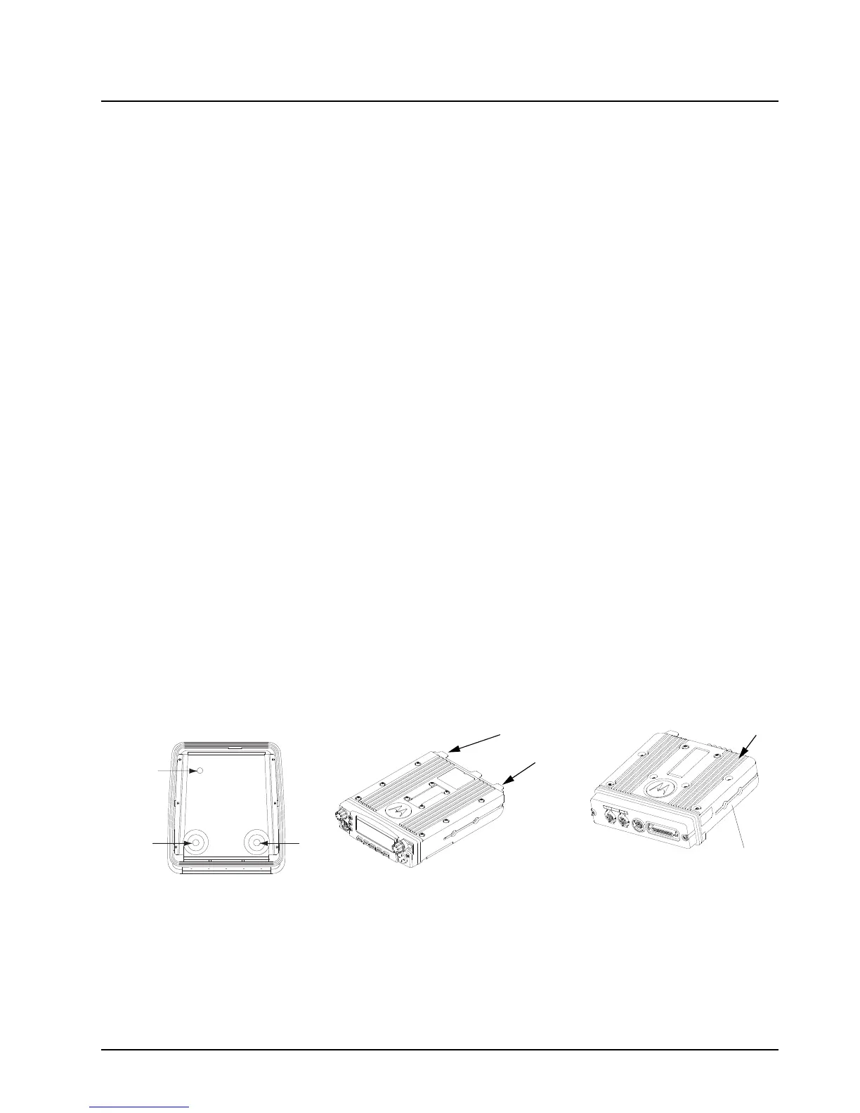
Figure 5-8. Location of Band 1 or Band 2 (Depending on the Antenna Port They Align to)
GPS
Band 2
Antenna
Band 1
Antenna
Band 1 Antenna Port
Band 2 Antenna Port
Top Cover for APX Radios
Antenna Port
ASTRO 25 Subscribers
APX 2500/APX 4500

 Loading...


