6878215A01
4-2 Options and Accessories Installation Remote-Mount Accessory Installation
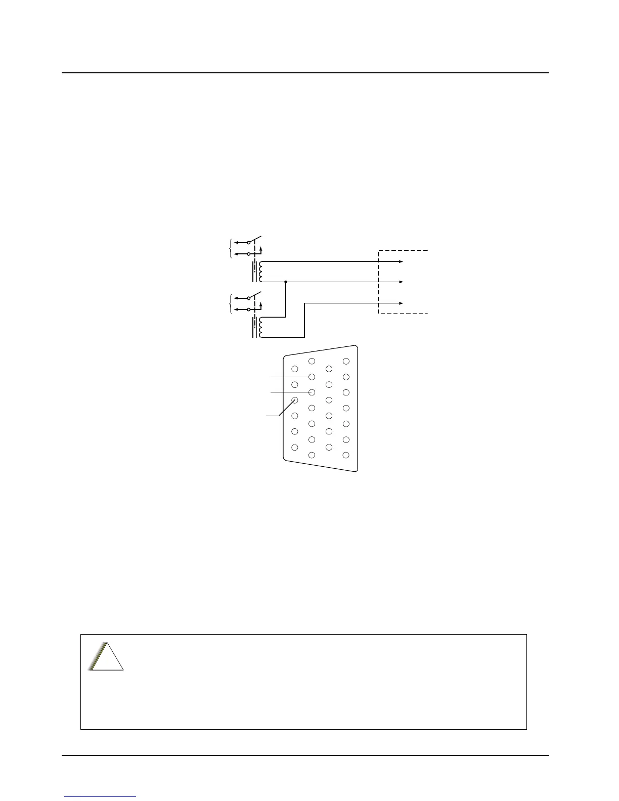
4.1.2 Dash-Mount Horn and Lights (External Alarms) Relays
NOTE: For installations that use the horn/lights option, select a suitable location for mounting
(normally under the dash) and, referring to Figure 4-2, perform the following procedure:
1. Horn Relay – Connect the relay contacts across the horn ring switch, typically found in the
steering column. Open the accessory cable connector and connect the two control wires
(male pins) into locations 18 and 24 of the connector.
2. Lights Relay – Connect the relay across the head lamp ON/OFF switch, typically found in
the steering column. Open the accessory cable connector and connect the two control wires
(male pins) into locations 19 and 24 of the accessory connector.
Figure 4-2. Horn/Light Wiring Diagram
4.2 Remote-Mount Accessory Installation
Perform the following installation procedure:
1. Select an appropriate place to mount the option or accessory hardware.
2. Route the accessory-to-control head cables under floor coverings or behind panels so that
the vehicle occupants do not snag or break the wires.
3. Attach wires from the accessory to the appropriate wire on the VIP cable (see Table 4-1 and
Table 4-2).
The radio is sold with correct accessory cables and jumpers in order to have
emergency de-activated by default, regardless of the setting in CPS. However, if
cables are not used, or if jumpers are removed without replacing with an emergency
accessory button/switch at one of the accessory ports, the radio will power-up upon
the application of A+. The display may not show an indication that the radio is on, and
this can result in an incorrect operation of the radio as well as excessive current drain
of the vehicle’s battery when the engine is off.
CONNECT
ACROSS HORN
RING SWITCH
CONNECT
ACROSS HEAD
LAMP SWITCH
SPST
N.O.
RELAY
12V COIL
12V COIL
VIP OUT 1
SWB+
VIP OUT 2
SPST
N.O.
RELAY
ACCESSORIES
CONNECTOR
PIN 18
PIN 24
PIN 19
SWB+
VIP OUT 2
(LIGHTS)
VIP OUT 1
(HORN)
1
7
8
14
13
20
21
26

 Loading...


