6878215A01
Motorcycle Radio Installation Installing the Emergency Switch Option 5-25
5.12 Installing the Emergency Switch Option
Use the two-conductor, green/black cable which has as one end terminated with two contacts (part
number 3080221P02) and which is supplied with this W688 Motorcycle Emergency Push Button.
Disconnect the emergency switch shorting plug from the accessory cable. Replace the shorting wire
of the shorting plug with the terminated end of the green/black emergency cable. Reconnect the plug
to the accessory cable.
5.13 Installing the External Alarm Relay Option
The motorcycle radio is offered with only one optional relay connection. If both horn and lights are
required, wire a second relay coil parallel to the first relay. Use the two-conductor green/black cable
which has one end terminated with two contacts (part number 3080221P02) and which is supplied
with this W116 Motorcycle Alarm Relay Option. Insert the contacts into positions 3 and 4 of the
emergency shorting plug of the accessory cable. Refer to Figure 5-23.
5.14 Installing the Headset Accessory
A six-position connector on the accessory cable has been made available for connecting a headset
accessory. Headset manufacturers should be consulted for compatibility with the motorcycle radio
prior to purchase and installation of the headset. To install, disconnect the headset shorting plug.
Remove the headset shorting wire from the headset shorting plug. Terminate the contacts provided
to the applicable wires of the headset cable. Insert the terminated wires into the headset shorting
plug per the contact positions illustrated in the typical headset schematic found in this manual.
Reconnect the terminated headset shorting plug to the accessory cable.
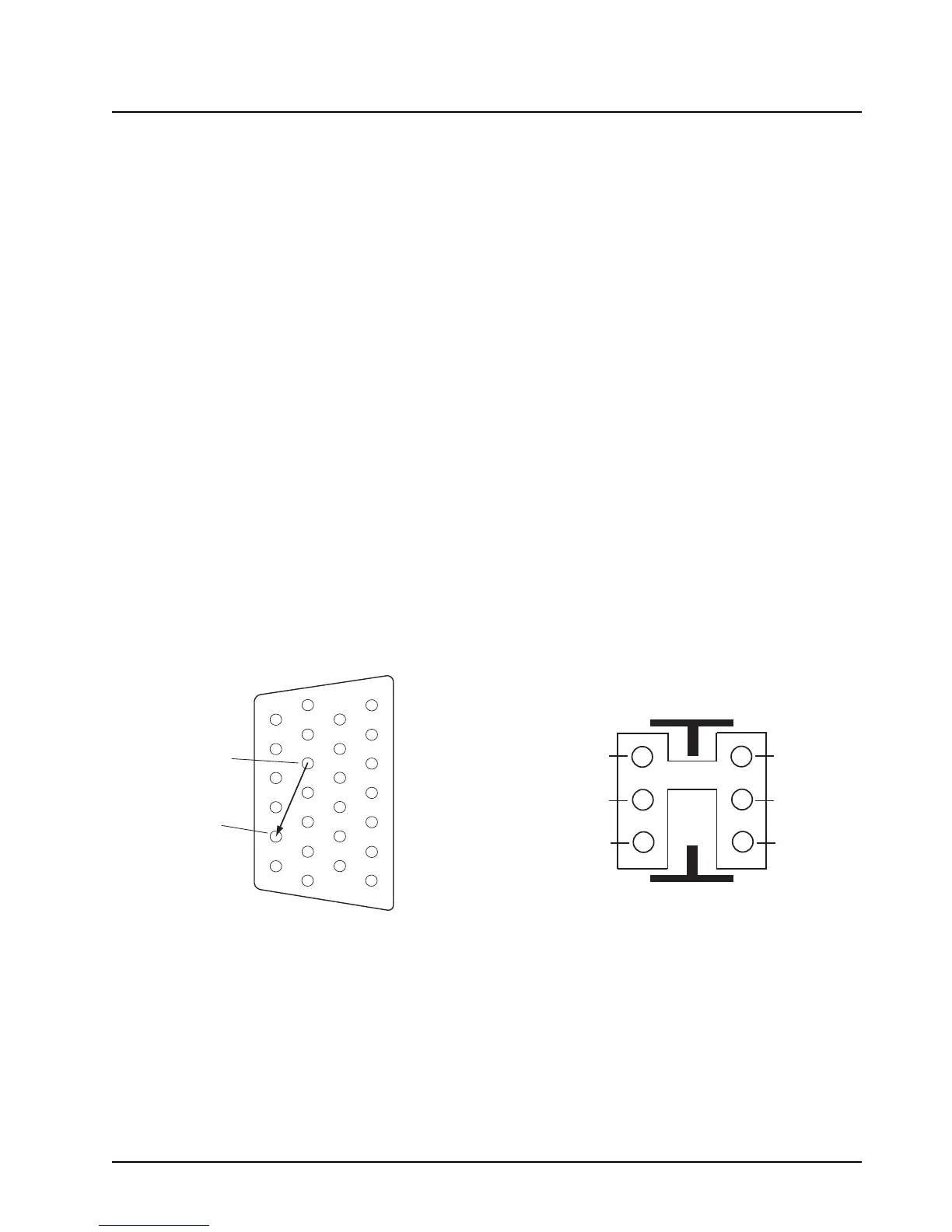
When upgrading from an APX mobile radio, the existing headset cable HLN6890 requires these two
pins to be swapped (see Figure 5-18). The other motorcycle headset cable with this pin change is
3080010R04.
Figure 5-18. Motorcycle Wiring Harness Rework
J2, BACK OF RADIO
Insert into Pin 22
(Monitor)
Remove from Pin 1
(VI P OU T 1 )
1
7
8
14
13
20
21
26
Rework for Handlebar HUB operation when
upgrading existing cable HLN6890.
(Female-Pins)
1
3
5
6
4
2
SPK -
VIP OUT 1
AUX_MIC
SPK +
GND
AUX_PTT

 Loading...


