6878215A01
2-30 Standard Configurations Radio Mounting
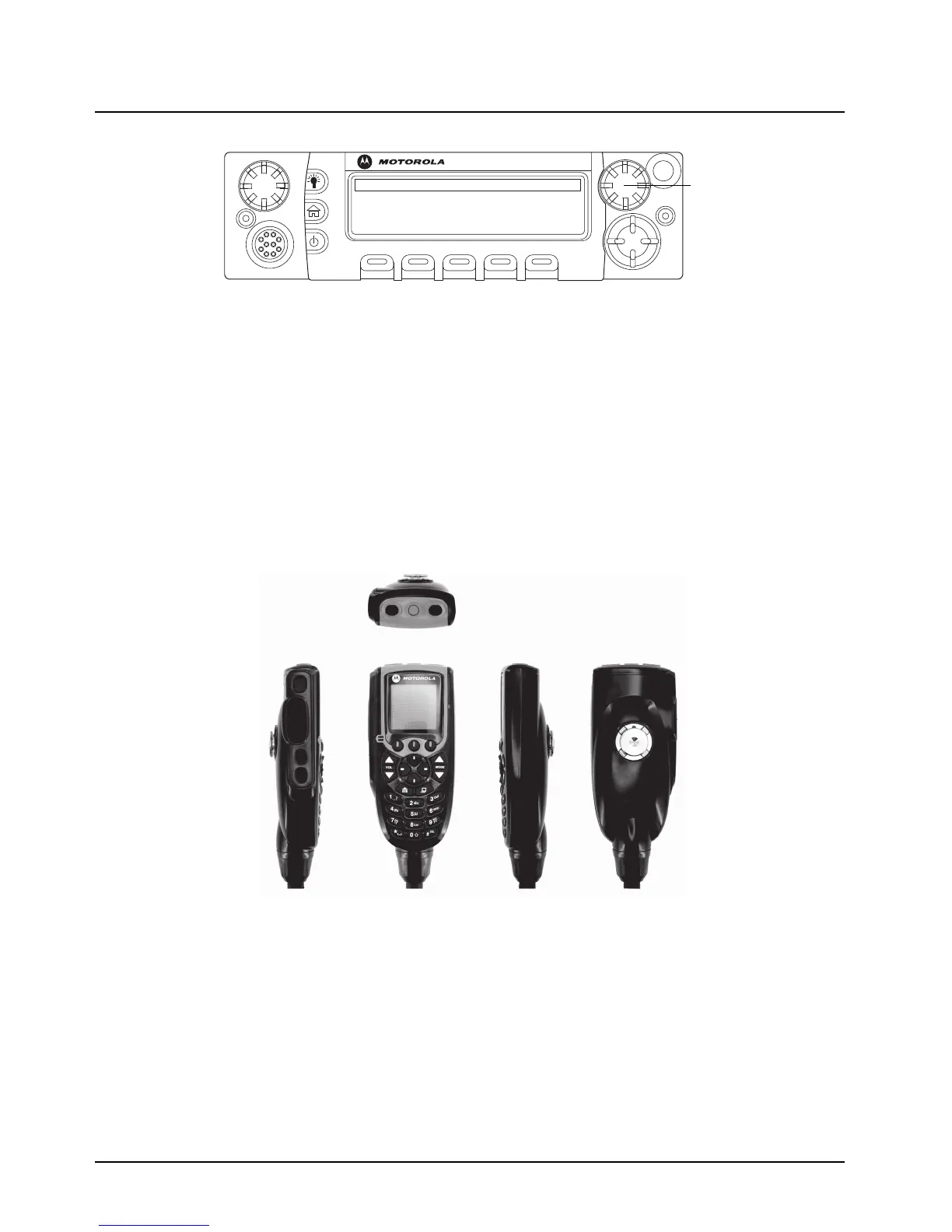
Figure 2-35. APX Mobile O5 Control Head Front View – Mode Knob
5. Repeat steps 1 to 4 above to set the ID of the remaining control heads.
NOTE: In Multiple Control Head (MCH) installations, the yellow ignition sense wire must be
connected to the head assigned ID # 1.
2.2.2.6 O3 Control Head and Remote Mount Cabling
Choose a mounting location for the radio, considering accessibility, and control and antenna cable
lengths. The control head extension cable and the accessories cable should be installed and routed
properly to avoid complications. Route the cables in the vehicle’s wiring troughs (where available) or
route the cables where they are protected from pinching, sharp edges, or crushing. One suggested
route is along one side of the driveshaft hump under the carpet. Use grommets in any holes where
the cable passes through metal panels.
Figure 2-36. O3 Control Head
The recommended mounting surface for the control unit is on the center console. Figure 2-38 shows
how the hang-up clip control head, and cables should be installed for the O3 control head.
NOTE: Connector-protective covers are provided with the radio. They should be used for added
environmental robustness.
O5

 Loading...


