Monitor System Access and Performance
298
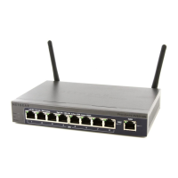
ProSafe Wireless-N 8-Port Gigabit VPN Firewall FVS318N
This section describes steps 2 through 4, using the topology that is described in the following
table:
Configure Gateway 1 at Site 1
To create a gateway-to-gateway VPN tunnel to Gateway 2, using the IPSec VPN wizard:
1. Select VPN > IPSec VPN > VPN W
izard. The VPN Wizard screen displays.
2. Configu
re a gateway-to-gateway VPN tunnel using the following information:
• Conn
ection name. Any name of your choice
• Pre-shared
key. Any key of your choice
• Remote W
AN IP address. 10.0.0.2
• Lo
cal WAN IP address. 10.0.0.1
• Remote LAN IP Addre
ss. 192.168.20.0
• Remote LAN subnet
mask. 255.255.255.0
3. Click Apply to save
the settings.
To change the remote IP address in the VPN policy:
1. Select VPN > IPSec VPN > VPN Policies. The
VPN Policy screen displays.
2. Next to the policy name for the
Gateway 1–to–Gateway 2 autopolicy, click Edit. The Edit
VPN Policy screen displays.
3. In
the General section of the screen, clear the Enable NetBIOS check box.
4. In
the Traffic Selector section of the screen, make the following changes:
• Fro
m the Remote IP drop-down list, select Single.
• In
the Start IP fields, type 10.0.0.2, which is the WAN IP address of Gateway 2.
5. Click Apply to save
the settings.
Configure Gateway 2 at Site 2
To create a gateway-to-gateway VPN tunnel to Gateway 1, using the IPSec VPN wizard:
1. Select VPN > IPSec VPN > VPN W
izard. The VPN Wizard screen displays.
Type of address Gateway 1 at Site 1 Gateway 2 at Site 2
WAN IP address 10.0.0.1 10.0.0.2
LAN IP address 192.168.10.0 192.168.20.0
LAN subnet mask 255.255.255.0 255.255.255.0
LAN IP address syslog server 192.168.10.2 not applicable
 Loading...
